Custom PC Build
Introduction
Quite a few years ago now I decided to try and build a custom PC with water cooling and custom manufactured parts. I remember at the time being captivated by the trend of custom PC builds, by things such as the Murder Box and various other PC builds that prioritised aesthetics and craftsmanship in the final product. This is something that unfortunately is often missing in the mass produced PC space.
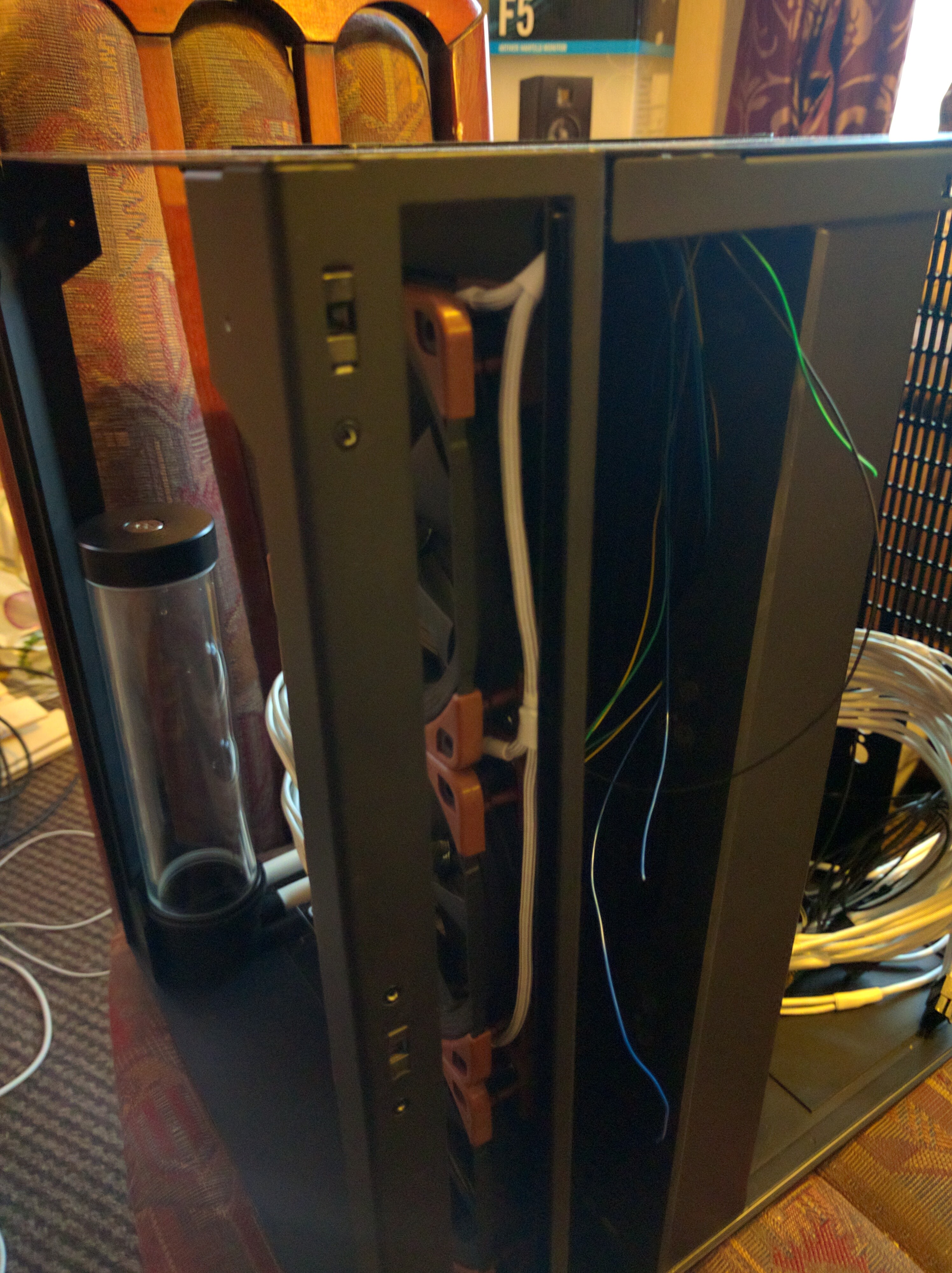
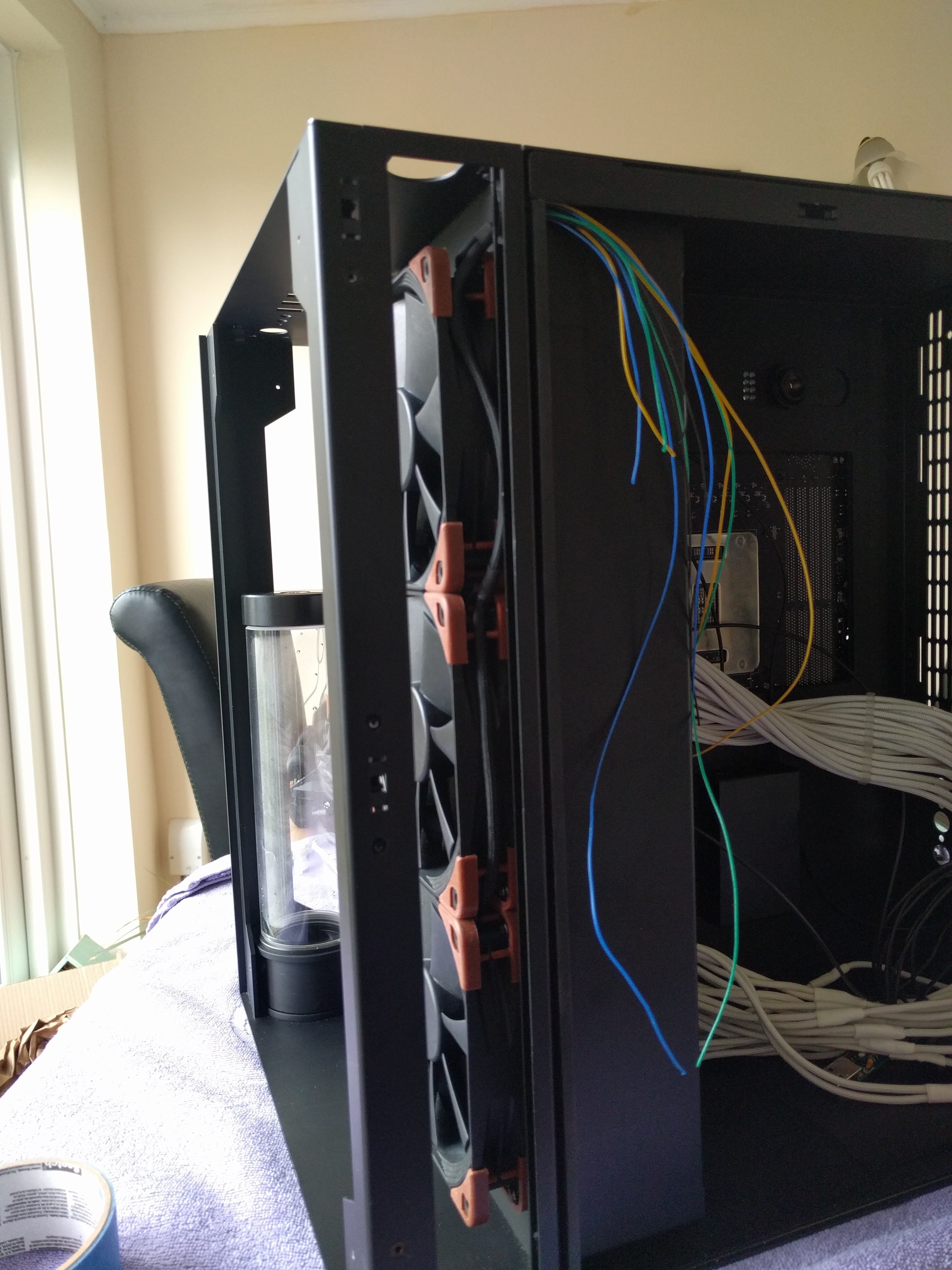
I decided to go with the Lian Li pc-08 case as it used high quality materials, such as tempered glass instead of plastic. It was a recently released case at the time thus no real custom PC builds had been done. There was one but I thought it made too many compromises, no doubt because I believe it was an Intel commission for a show and corners had to be cut to make the time. Below is an image of the only other PC I had seen at the time on the internet where water cooling was integrated into this case.
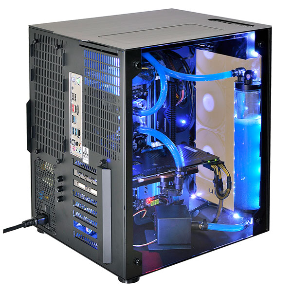
As shown in Figure 2 the build didn’t look particularly clean, with standard PSU wiring and the water pump being clearly visible in the front of the case even though there is plenty of room to hide it away. I decided that I wanted to address these issues, especially the water pump, along with making sure that everything was done to a high quality and even areas of the case that where not visible still being tidy and thought through.
Build Log
Water pump placement
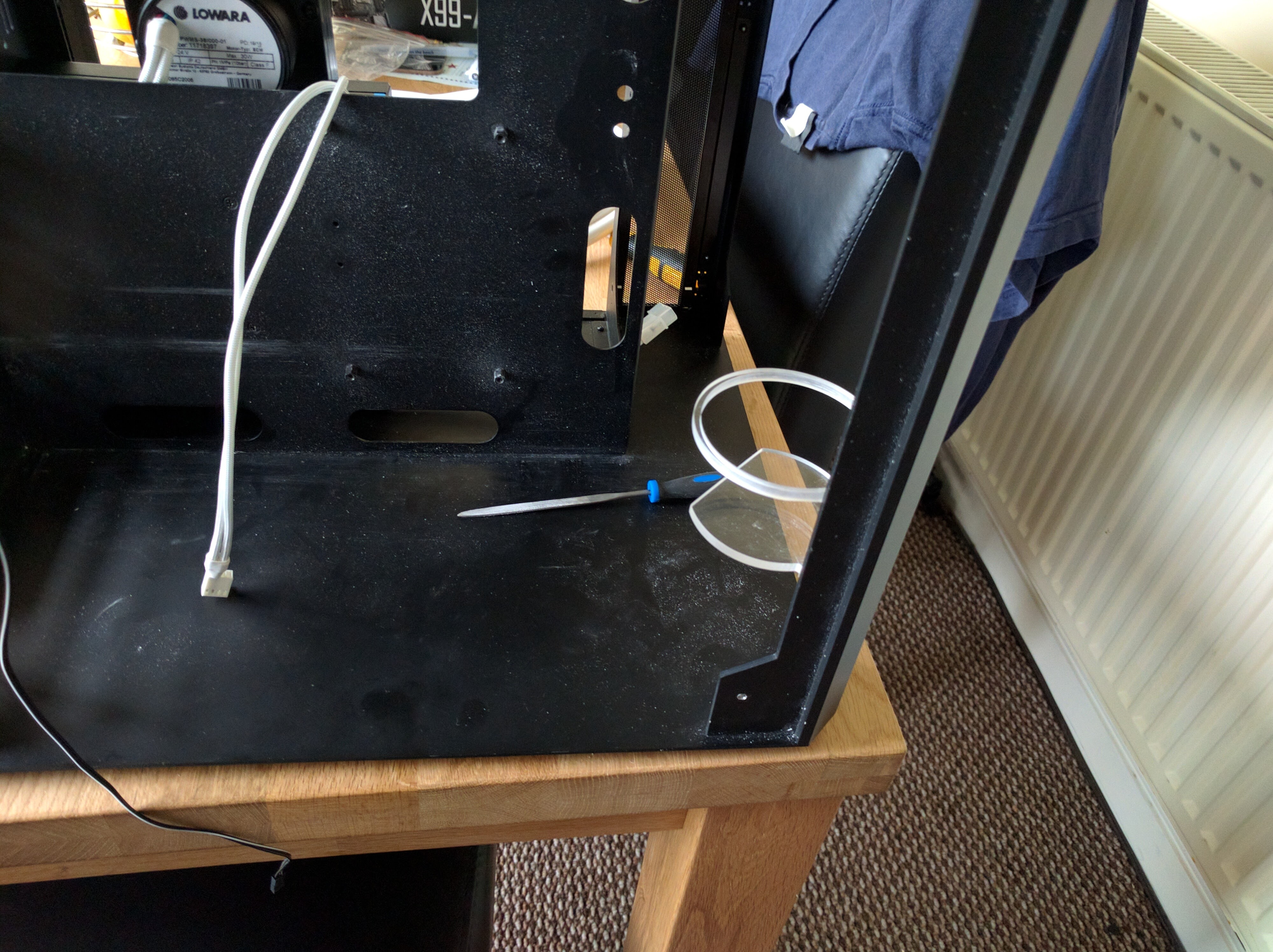
The first problem I wanted to tackle in the build was the water pump placement, as this was the most egregious problem of the CES build from Intel shown in Figure 2. There was lots to consider here with the pump needing to be mounted relatively low in the computer to make sure bleeding the water system was not too much of an issue. However in the rear compartment of the case the PSU sits at the bottom taking up all the room. With the reservoir I was using it was possible to mount the water pump just above the PSU, however there were no mounting locations so one would have to be made.
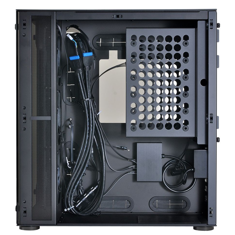
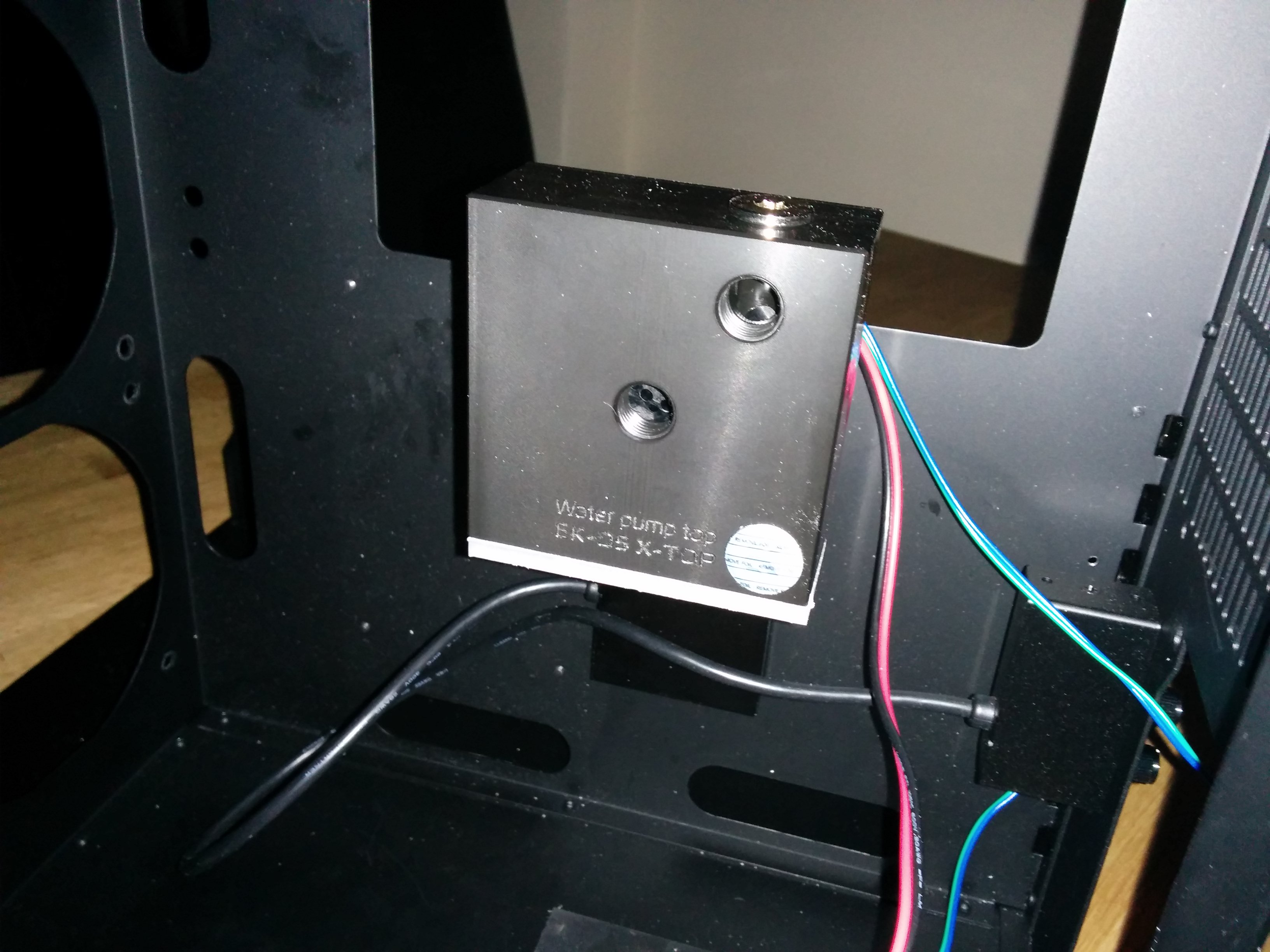
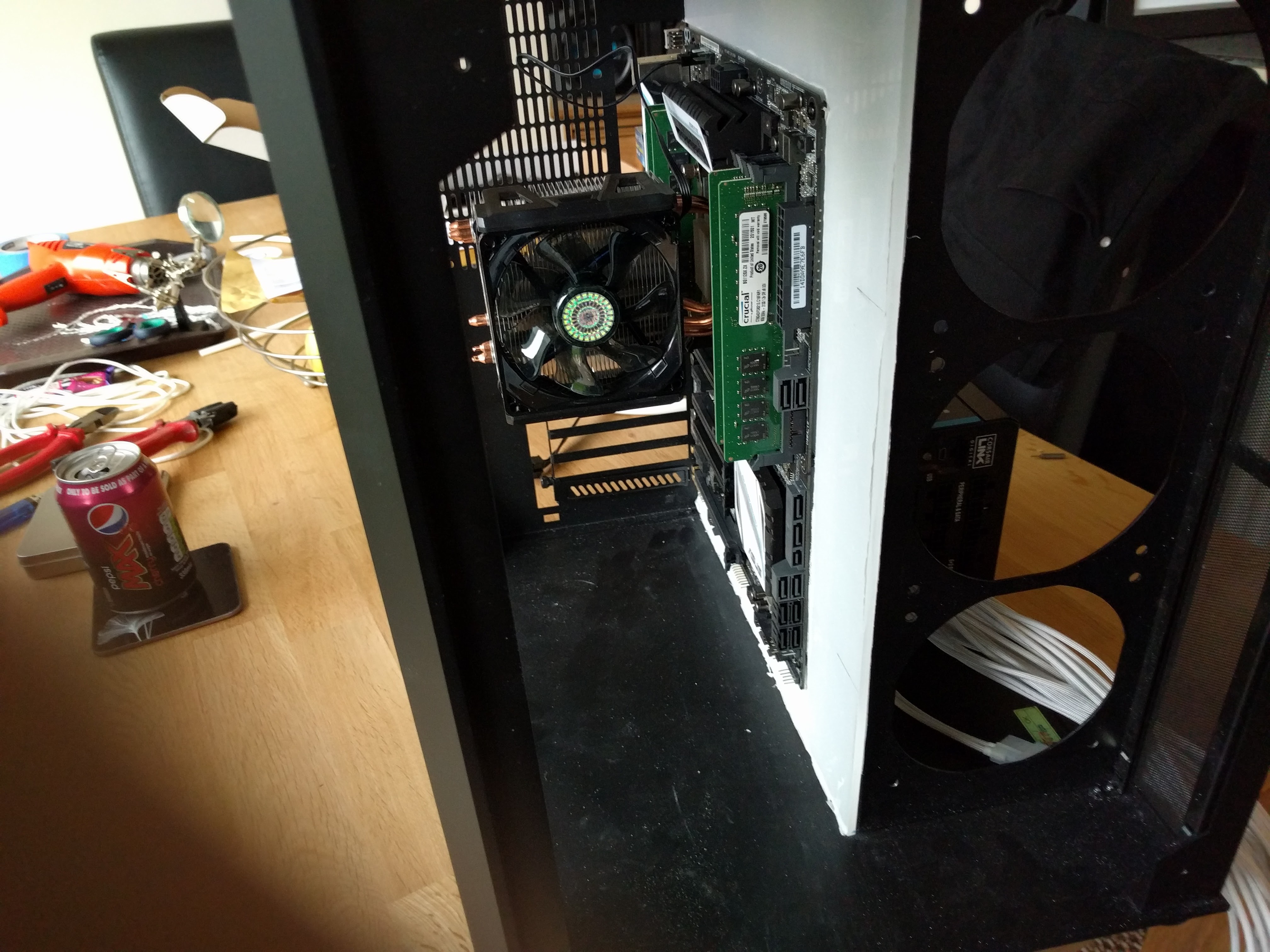
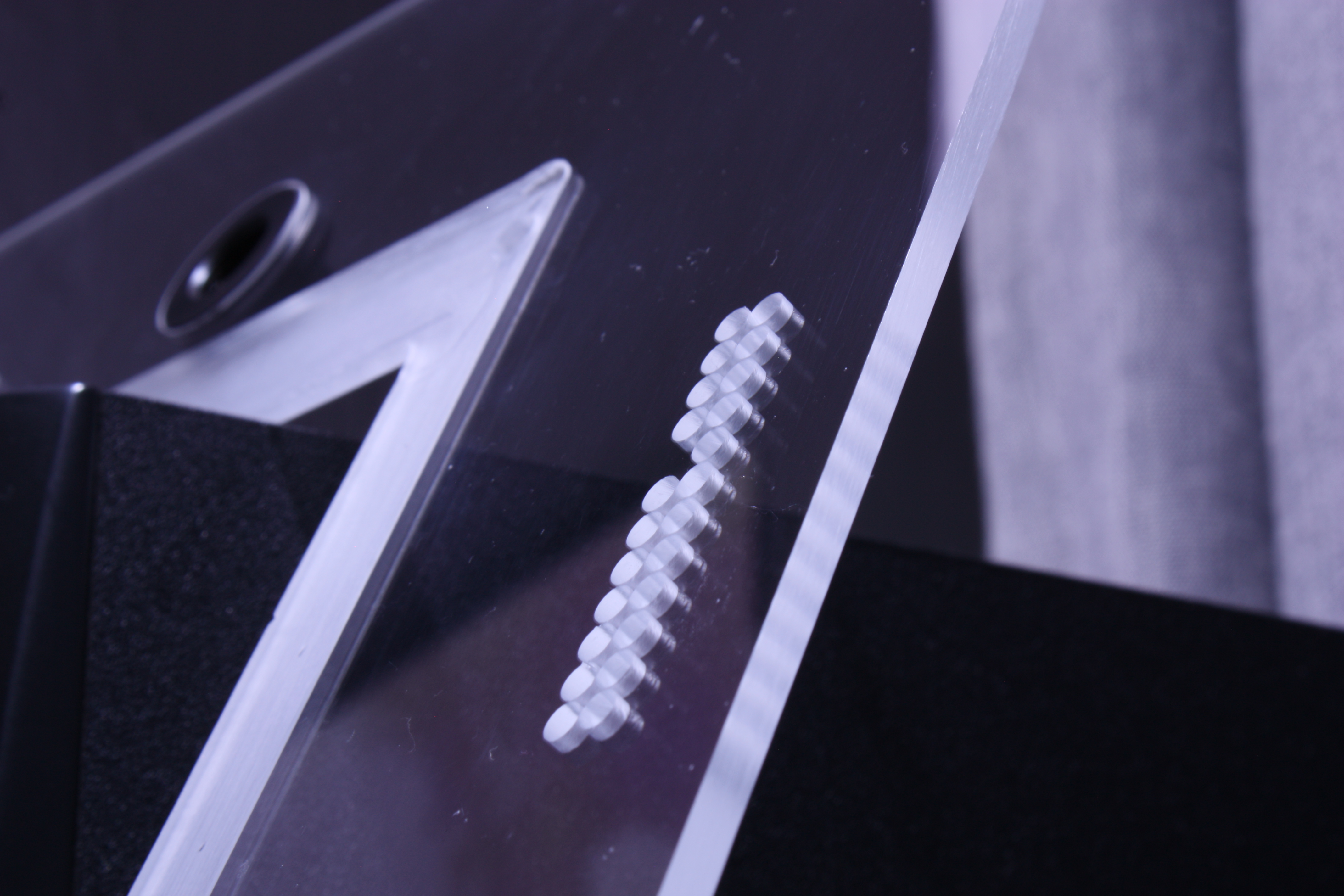
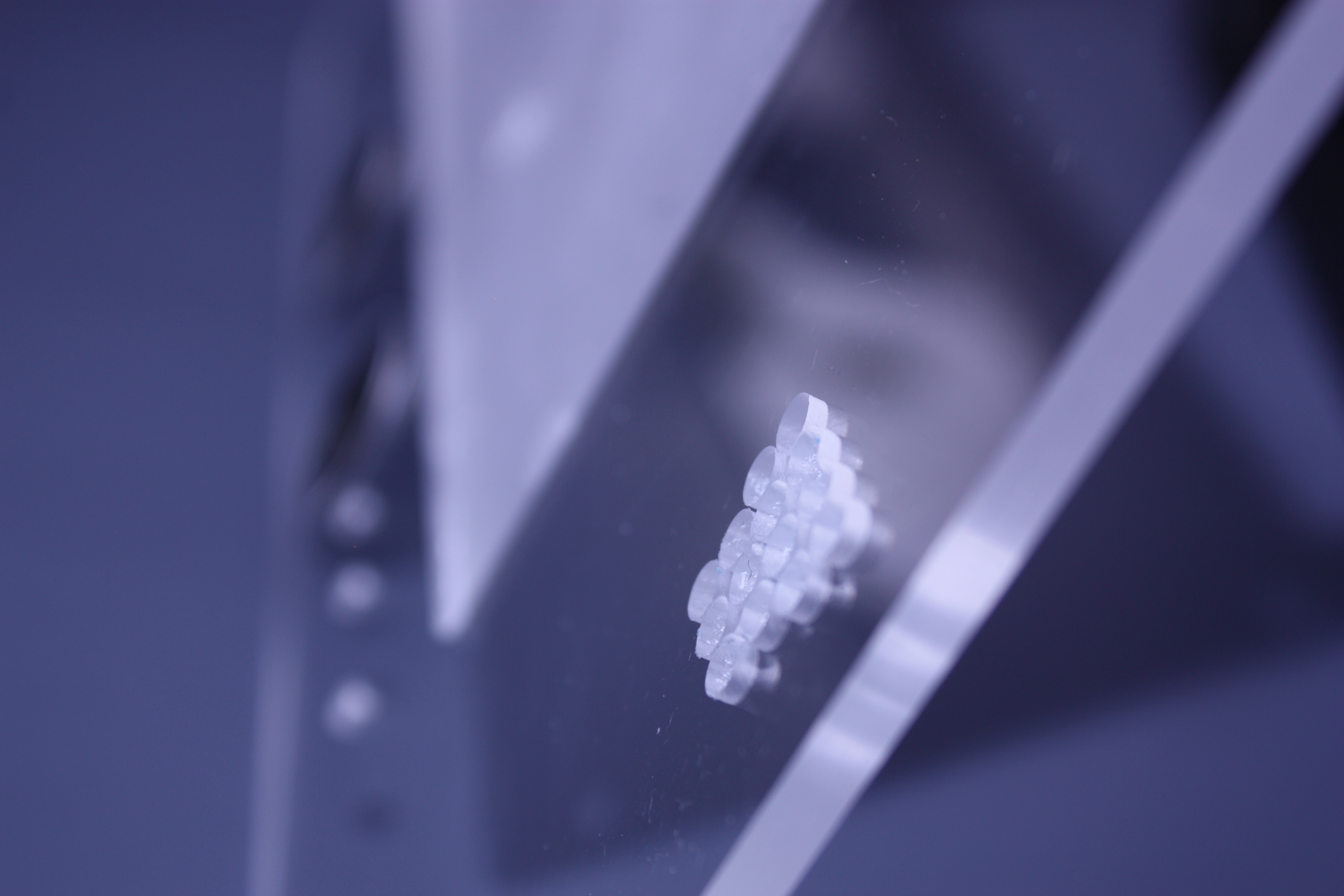
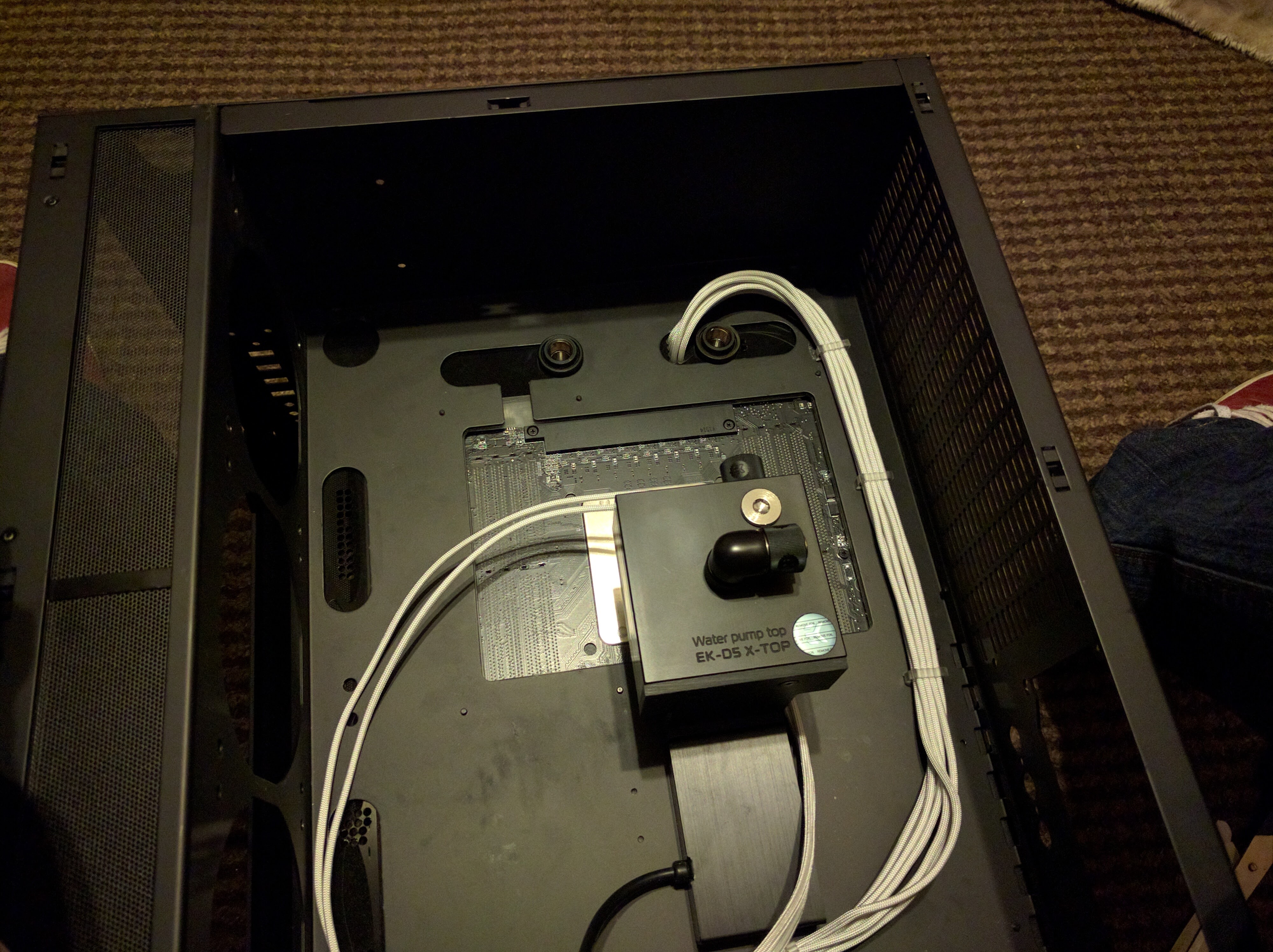
As shown if Figure 3 you can see that the PSU sits along the bottom of the rear cavity taking up all the room that would be ideal for a water pump. This is most likely why the pump was moved to the front of the case for the CES build. However I noticed that the RGB controller for the lights (which I wouldn’t be using, more on this later) was perfectly placed to allow for mounting of a bracket to have the water pump sit just above the PSU. I would also be removing the HDD cage in order to free up space as I was going to be using a 1TB PCI-e SSD for this machine anyway. This ended up being a pretty easy part to make on my small CNC machine, just two pieces of cut acrylic welded together. Below in the finished part.
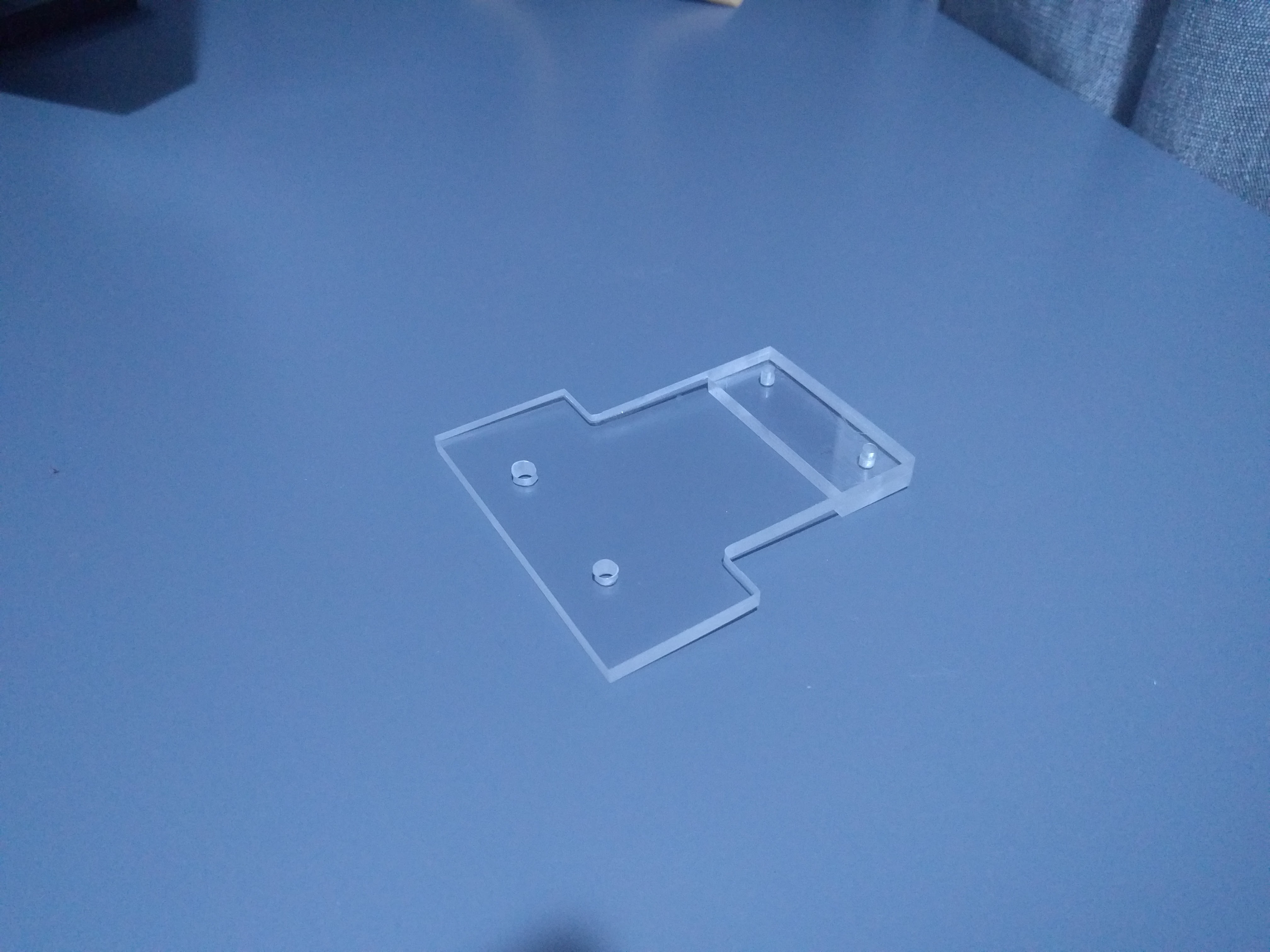
This part would later be painted black in order to better blend in, however in Figure 5 you can see how this bracket holds the water pump up within the back cavity, when the PSU is mounted there is a tiny gap between the bracket and the top of the PSU.
Reservoir Bracket
The next challenge was to mount the reservoir, in this case I actually liked the placement of the reservoir in the CES build. This was placed just in the corner of the front compartment so that it didn’t obstruct the view too much of the other components but you still see it plumed in. I wanted to make another custom bracket in the same method I had successfully used for the water pump. First I designed a bracket that could be made up of sandwiching three distinct acrylic parts (parts A, B and C) with a metal bar through the middle in order to add rigidity. These finished parts are shown below.
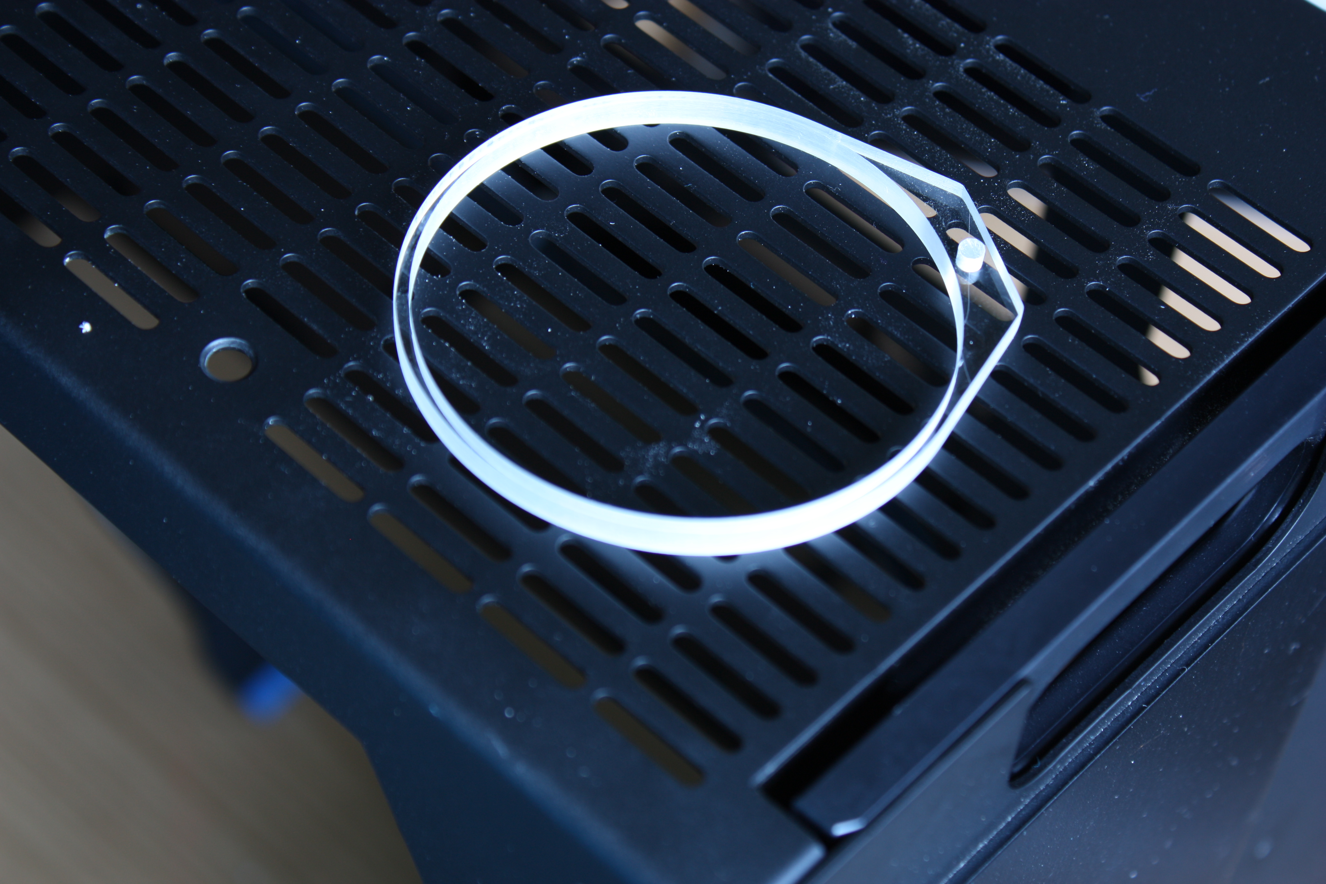
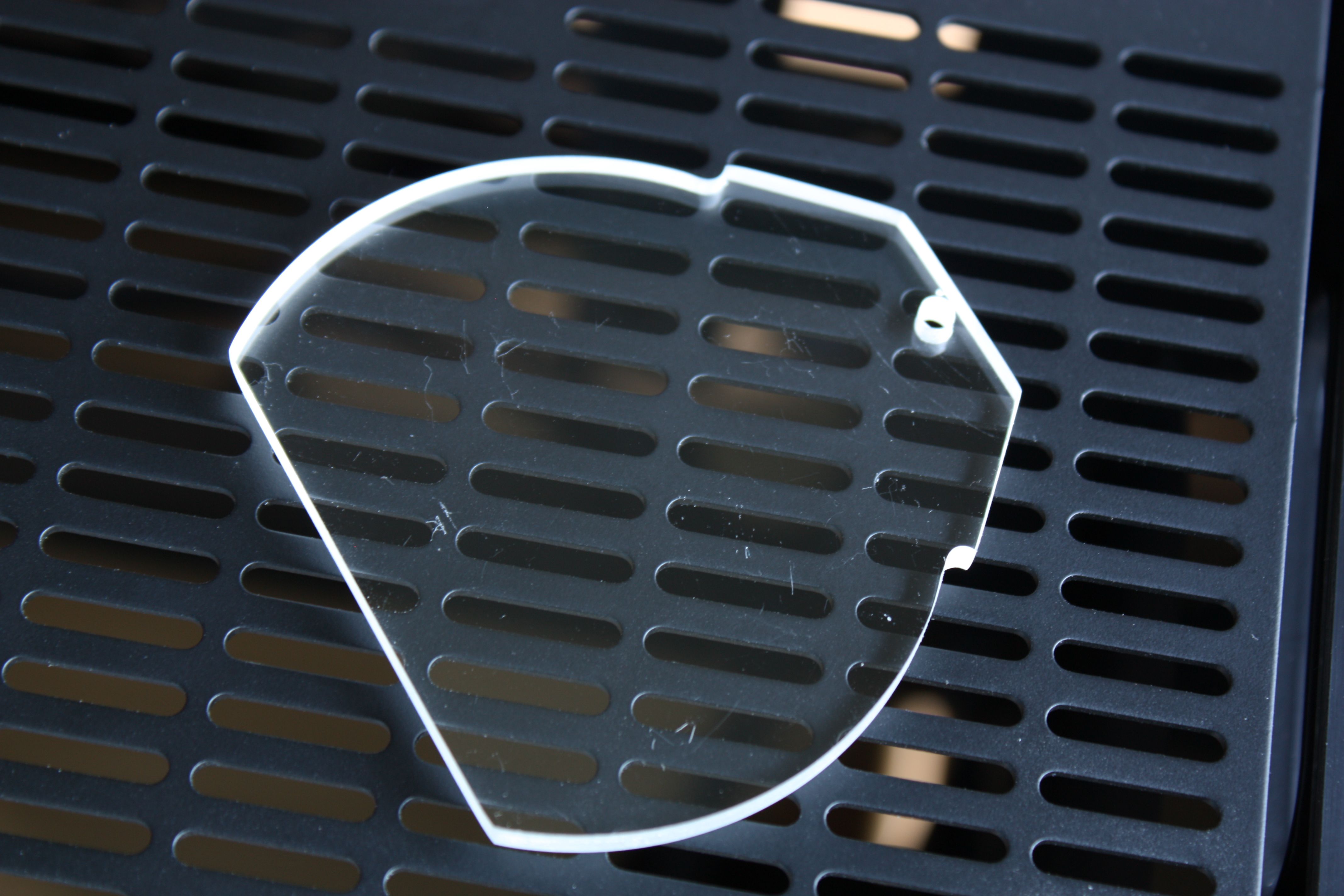
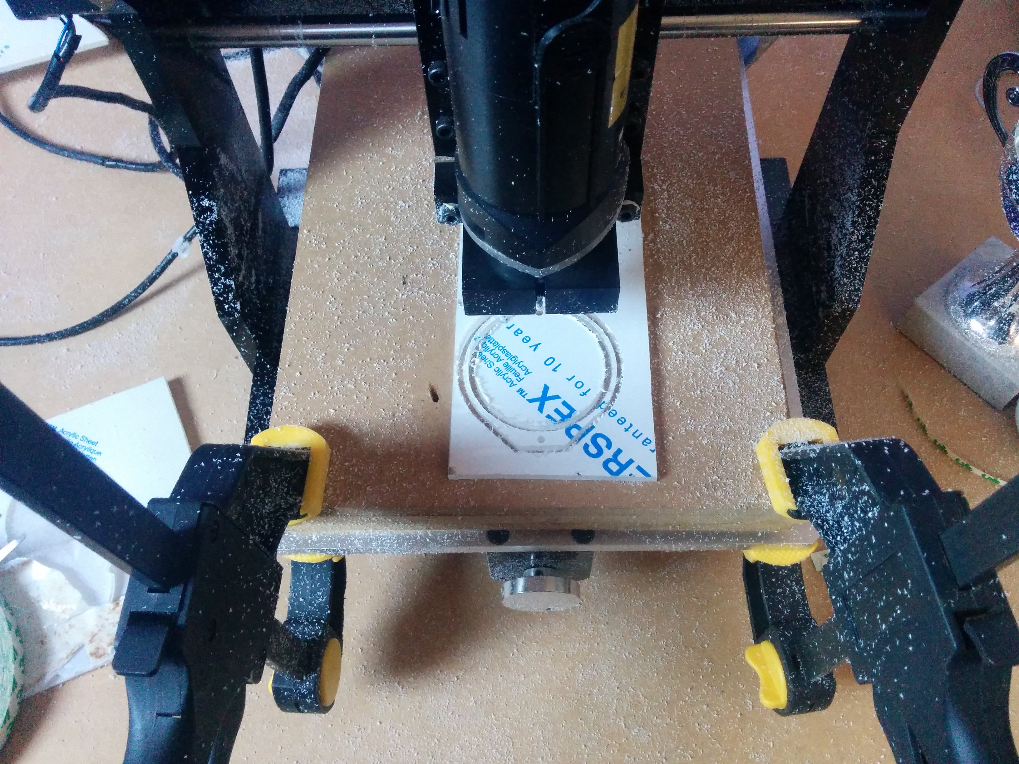
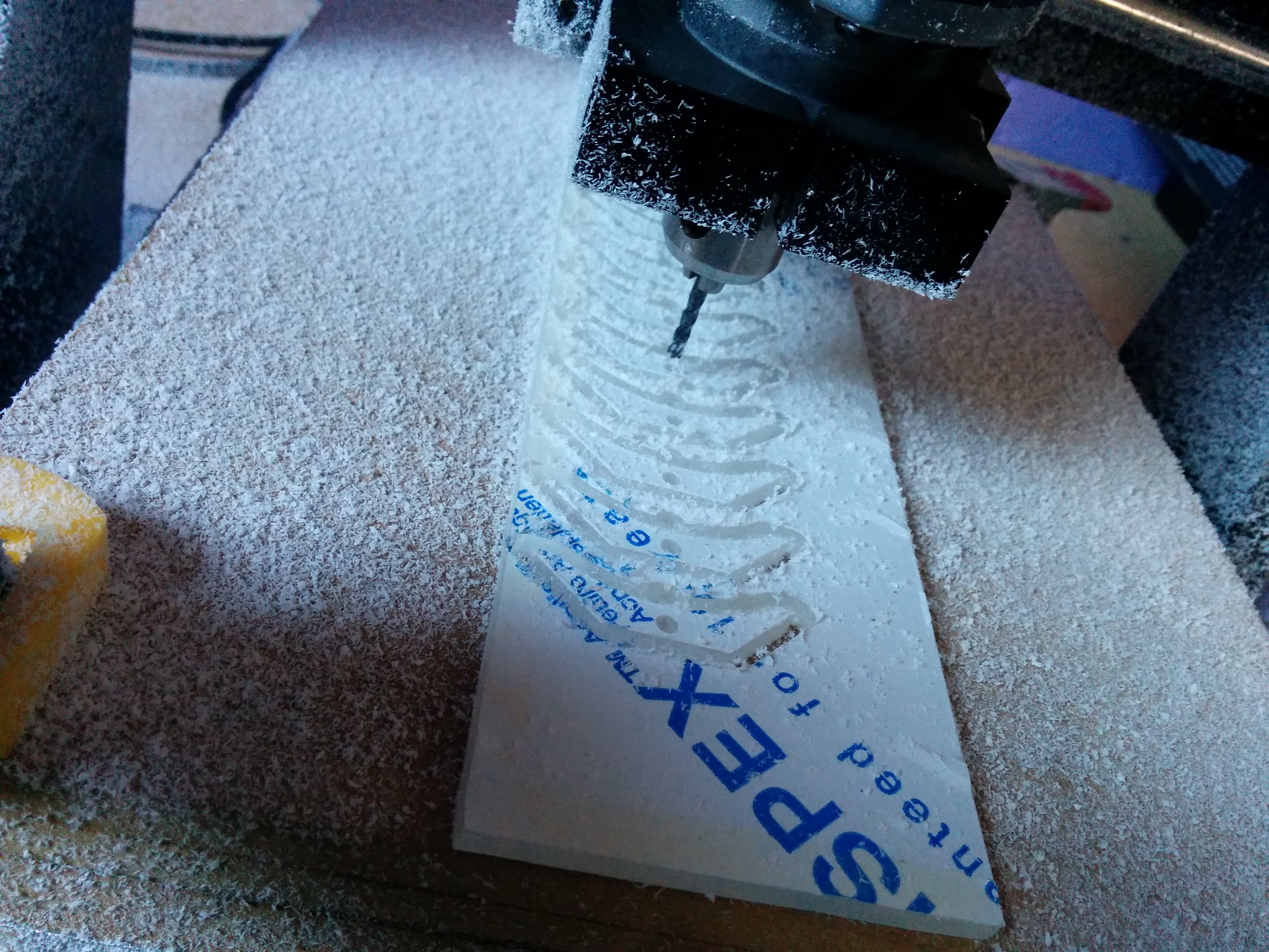
Again I used my small CNC machine to cut these parts as shown below. Where part A has finished being routed from the acrylic sheet.
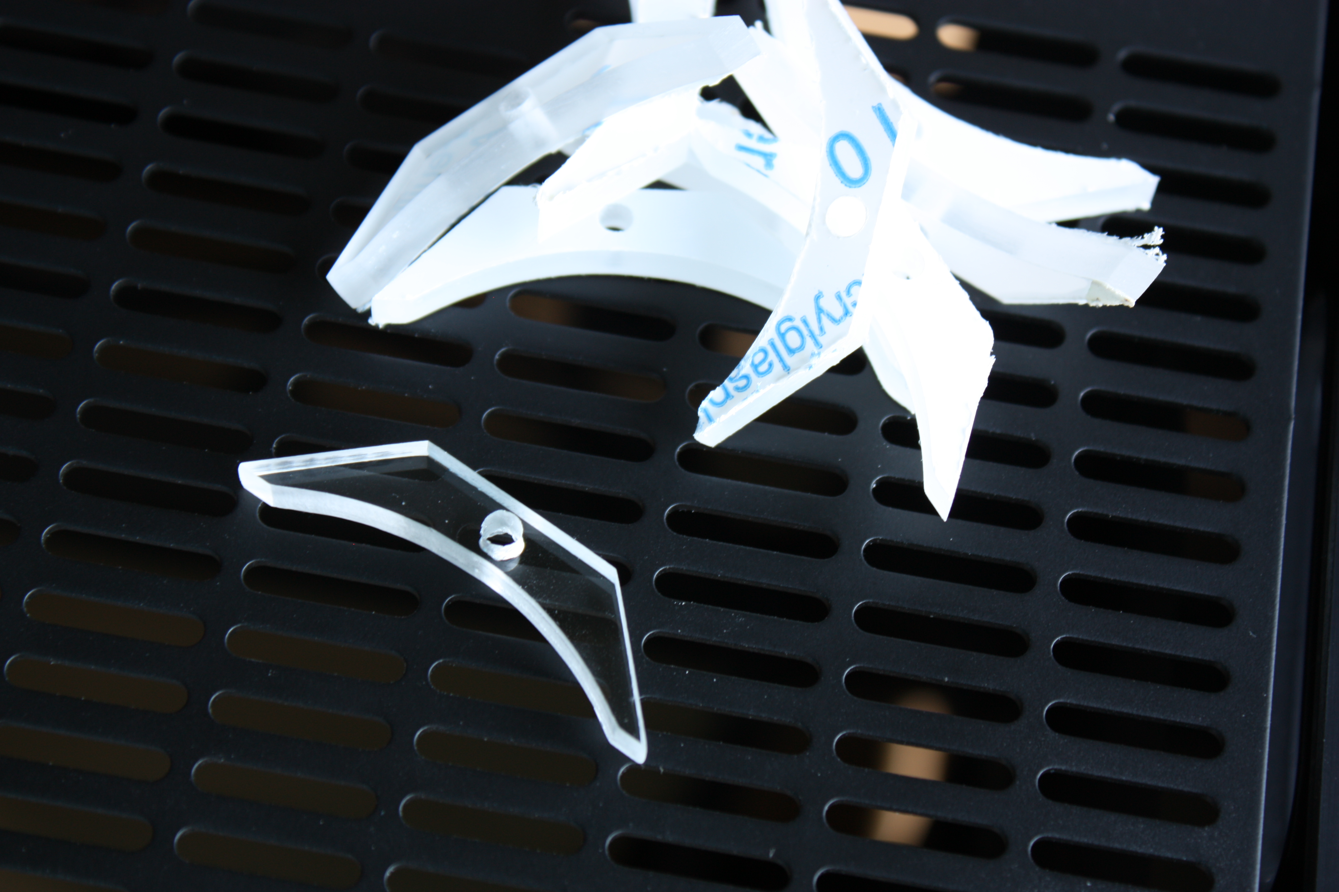
As I needed multiple of Part B in the design I stacked these and cut them all at once.
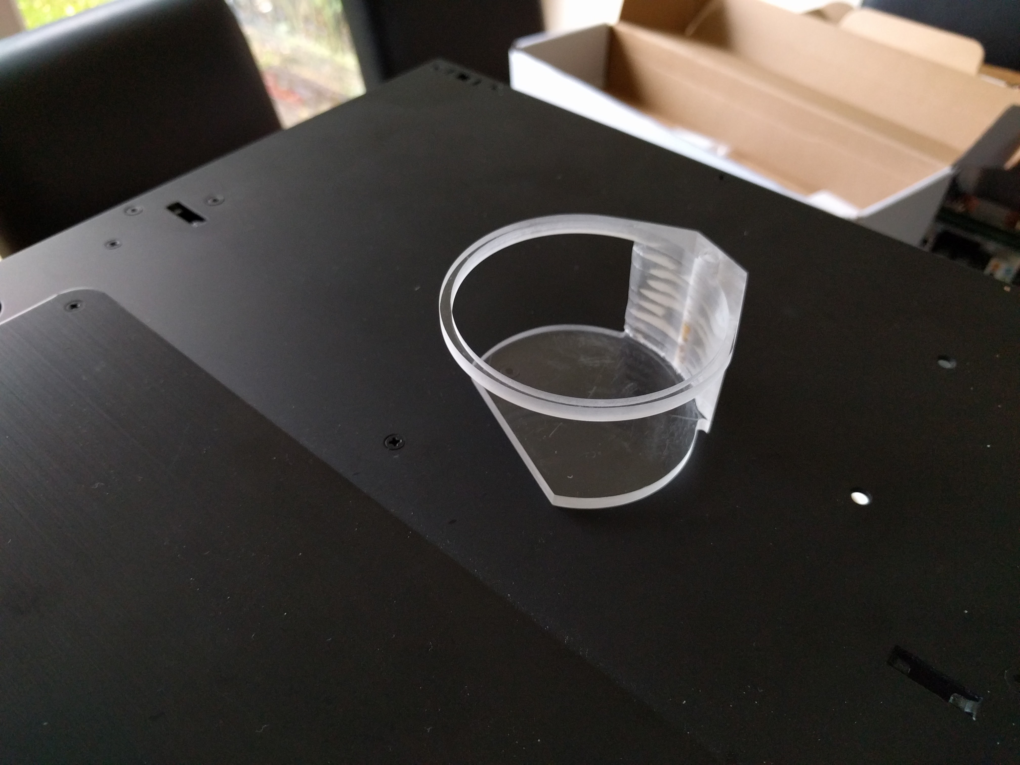
These separate components could then be welded together to make a single piece that can hold the reservoir from the bottom in the corner of the case.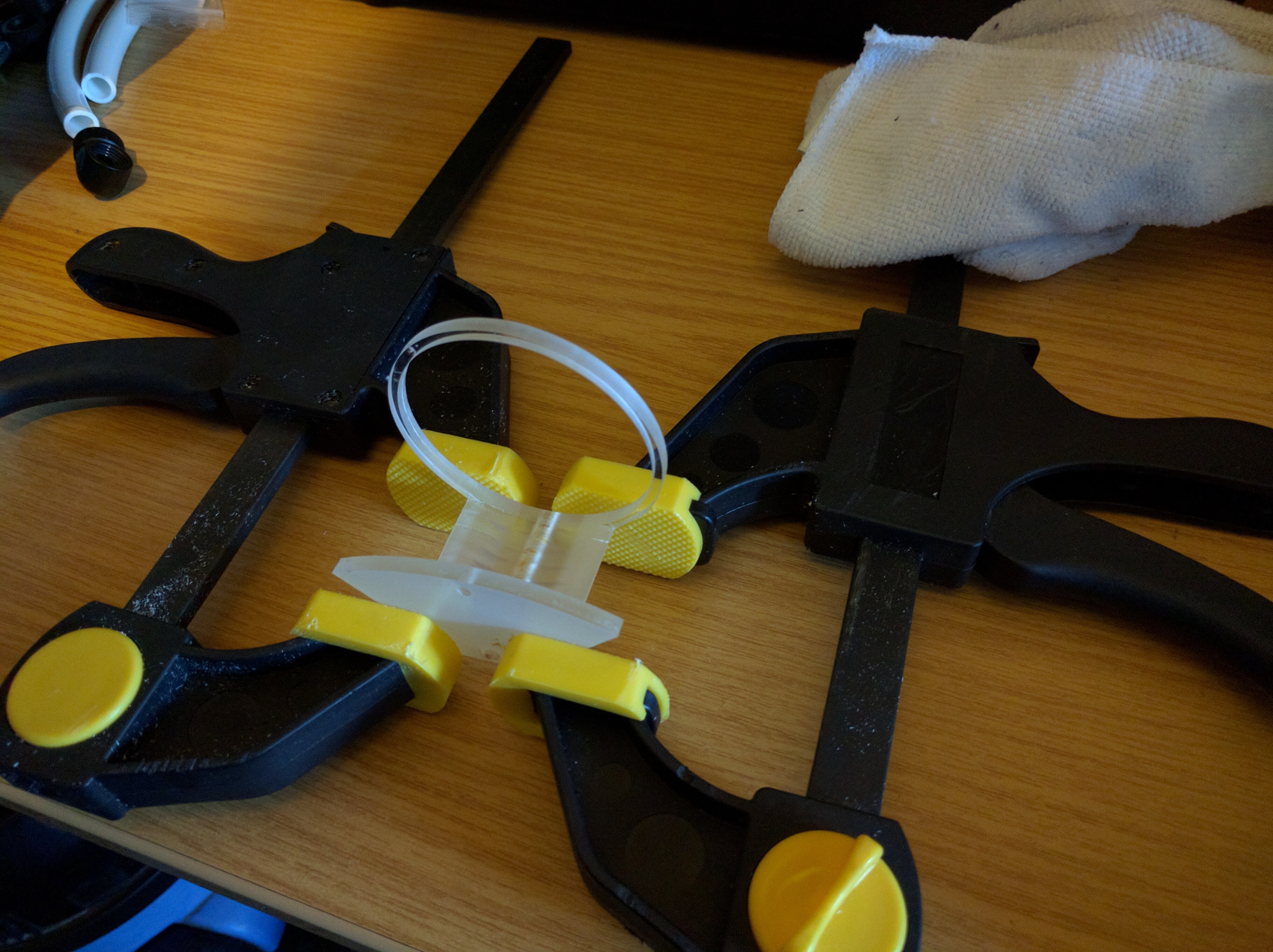
After welding I ended up with a finished re saviour as shown below. Those paying attention will note that this is not the same one as being show above this is due to the mount going through many iterations in order to get the finish and fit perfect, with a bottom plate designed to match the reservoir perfectly.
As mentioned earlier this was designed to allow for the reservoir to be mounted at any height by varying the number of plates underneath. Below we show a test fit before painting with the reservoir mounted high in the case.
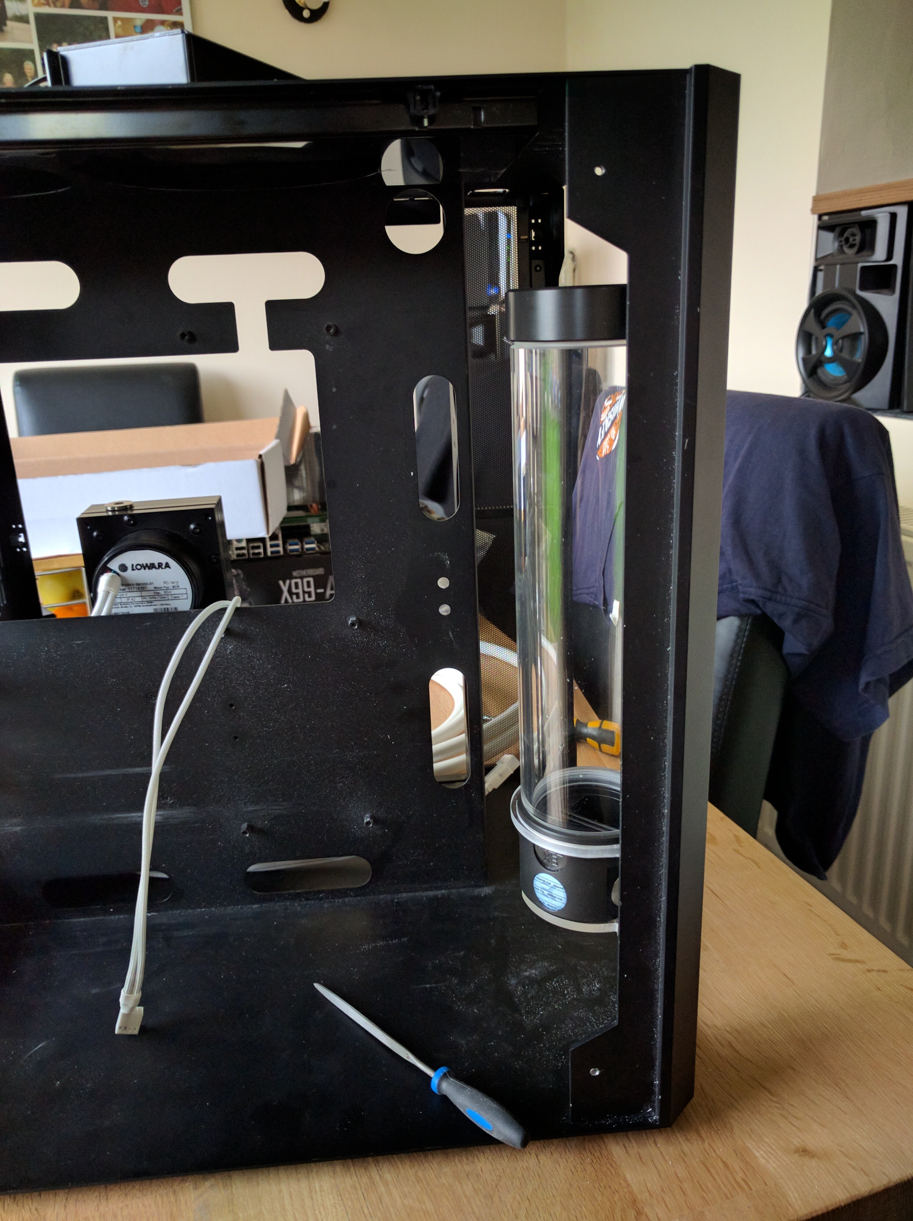
In the end I didn’t go with the reservoir mounted that high as it made the routing of the water pipes rather ugly without a nice way of making it look cleaner. This resulted in me deciding to mount the reservoir much lower. This does make bleeding the water system a bit of a pain however that is not something I have to do very often and I will have to look at the PC every day. This resulted in me dropping the reservoir as low as it goes making sure that a good portion is still above the water pump to prevent starvation.
Back Board
I wanted to make sure that every part of the build of this computer was thought through and that everything had it’s place and was considered. Especially with routing of cables and water pipes, with this often looking messy and having to conform to the case design in sub optimal ways. I decided to create a custom back panel with clear cutouts and passtroughs for the water pipes and cables being routed to the back compartment of the case. This ended up being the bulk of the build as it took a lot of time to design and finally build with the limitations of my CNC machine having to be worked around.
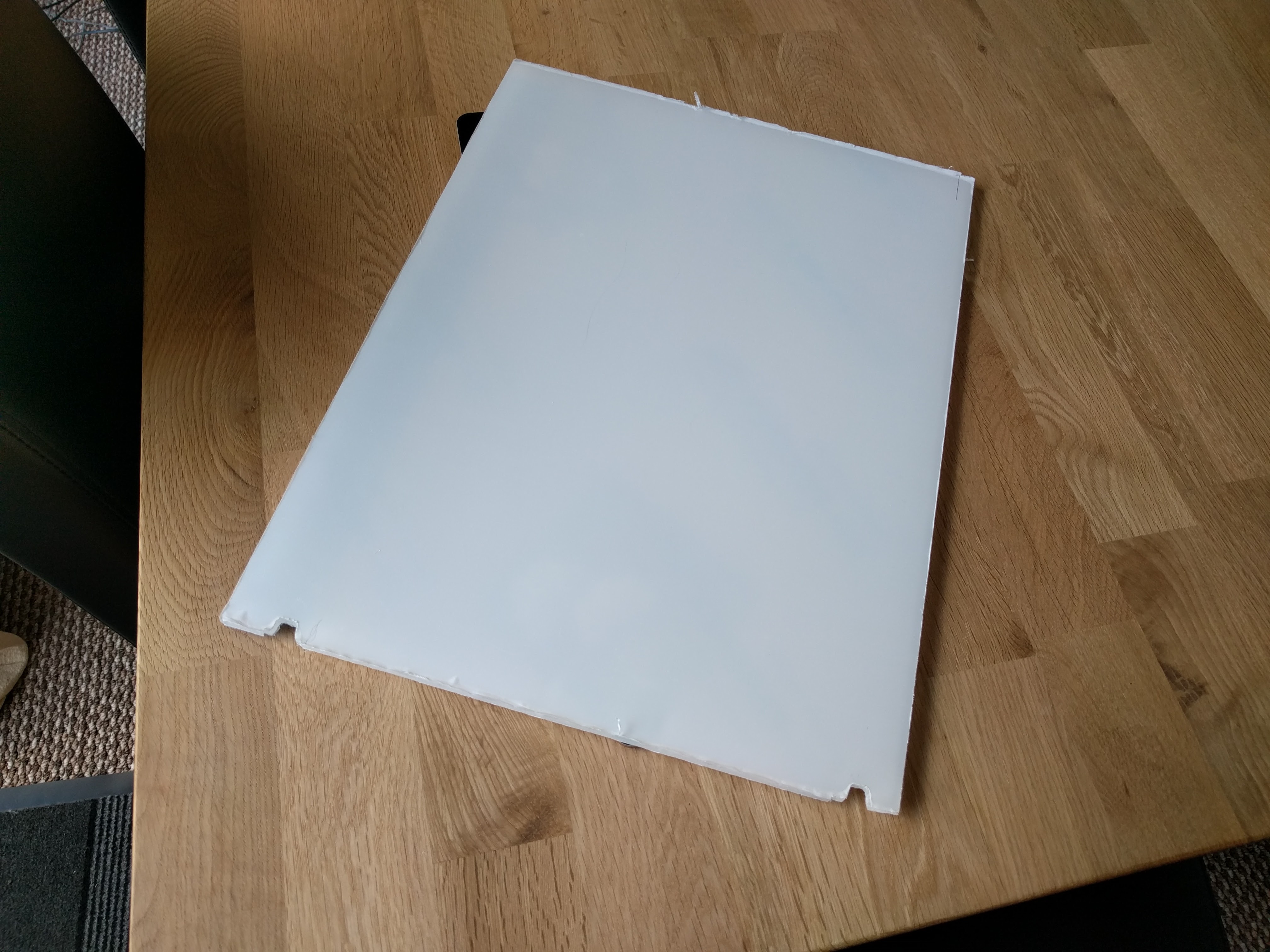
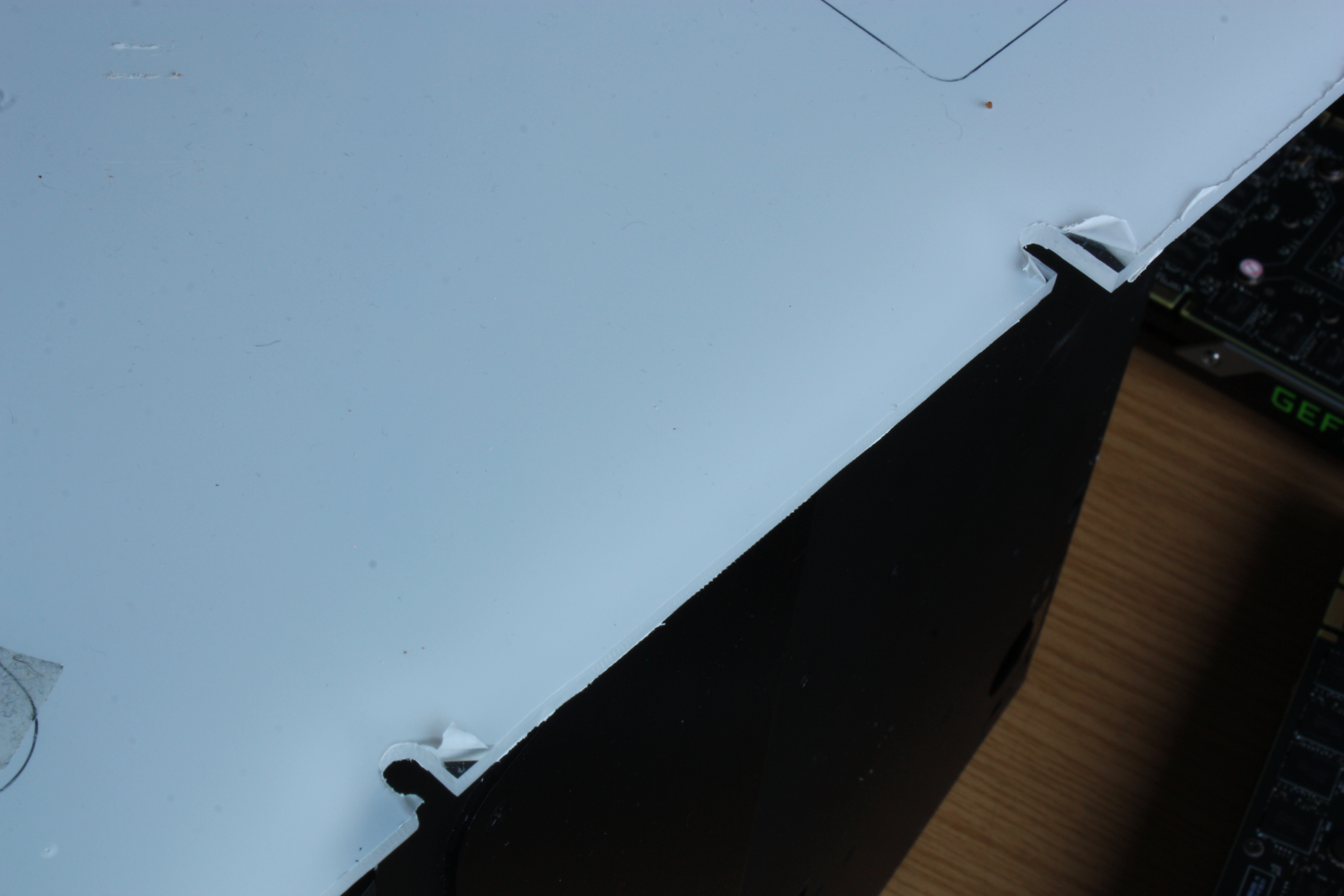
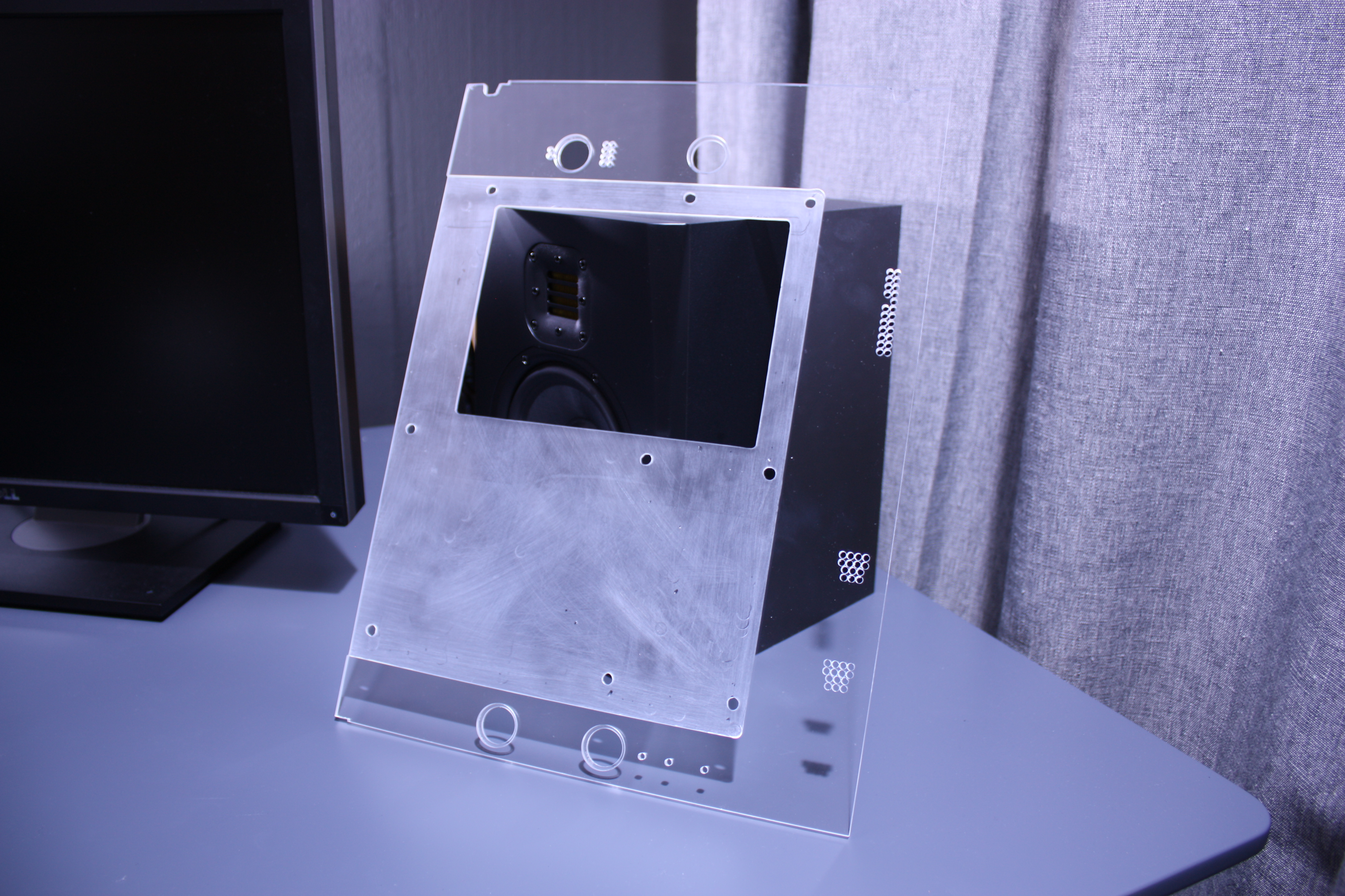
The first stage of this build was to hand cut a piece of acrylic that would fit perfectly into the front compartment of the PC where the motherboard is mounted. This was relatively easy although several custom notches where needed to fit perfectly around the edges of the case where the metal panels where riveted etc.
Some of these notches where intricate and where cut out on the CNC machine to give a nice finish. Such as for the PCI area that needed some space cut out to make a perfect fit, shown below.
Once the perimeter was fitting perfectly within the case I needed to hollow out an area for where the Motherboard would be mounted on stand offs, this would prevent the motherboard from shorting out on the backboard by giving enough airgap between the two. This was first measured out and marked on the acrylic where the standoffs where and the perimeter of the motherboard sat, as I would like a nice seamless fit between the end of the motherboard and the start of the raised backplane.
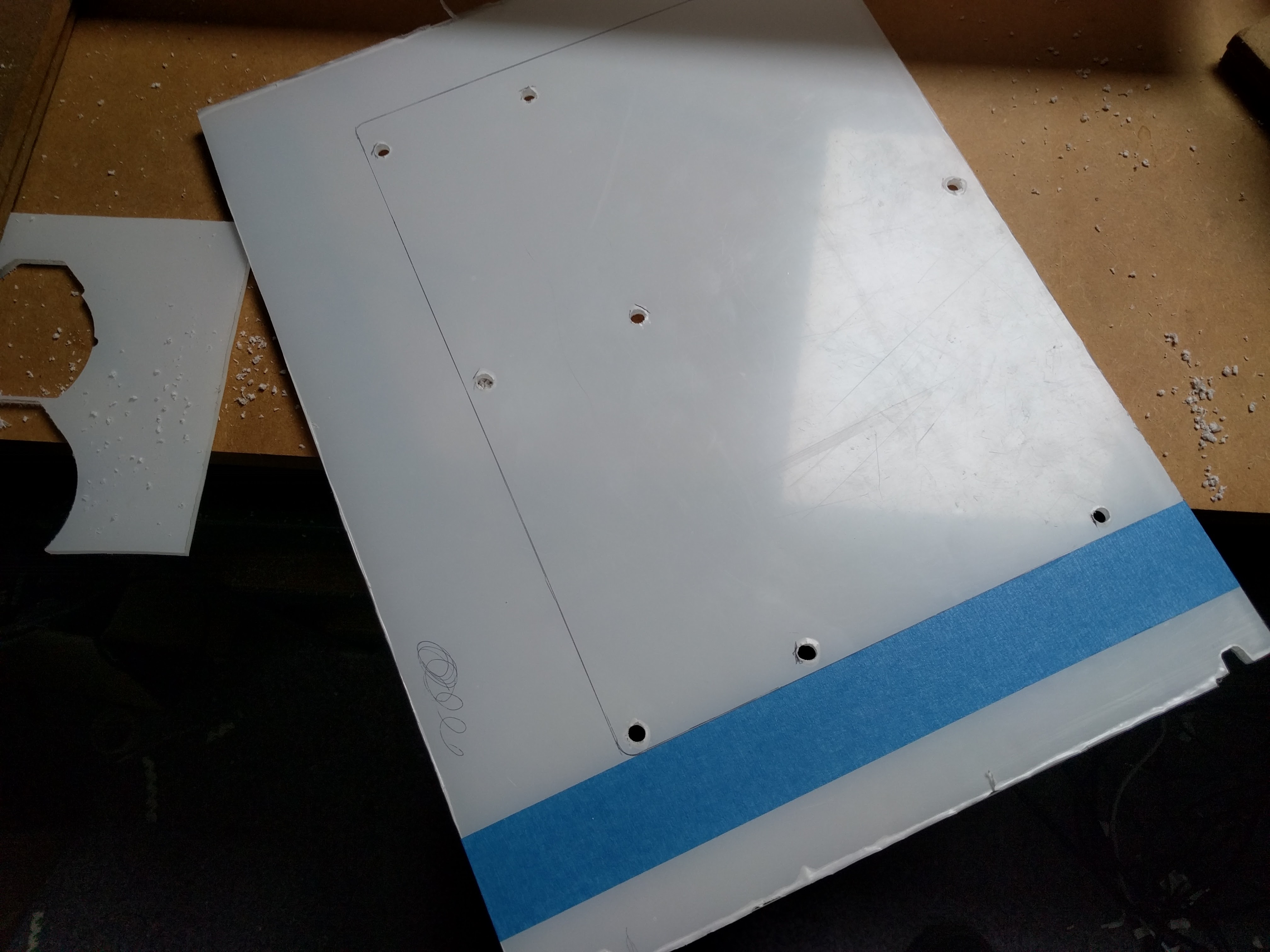
Routing out the motherboard location would have to be done by hand as this piece was too big to fit on the CNC machine, I would manage to cut some parts on the CNC shown later but this area was way too large.
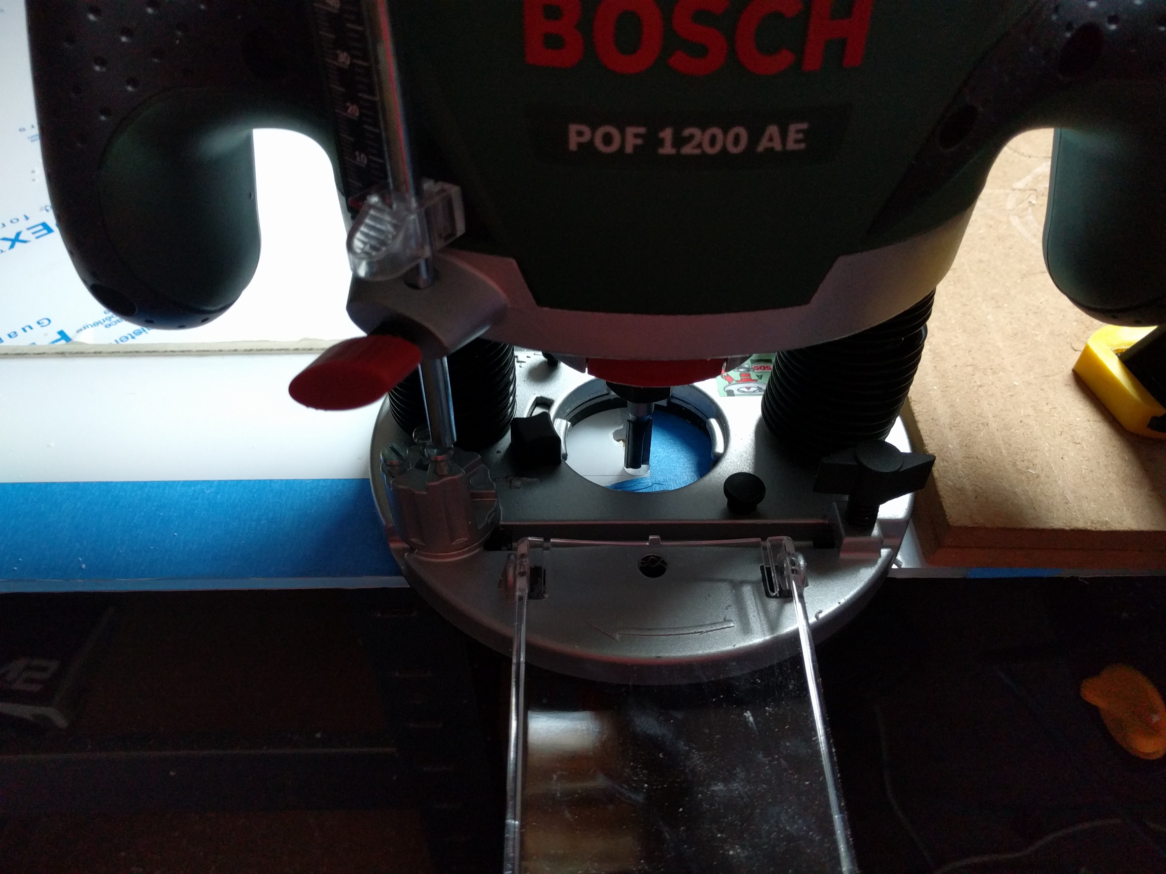
In order to route out the area I made use of a hand router and pieces of wood and acrylic to make guides to make sure that the edge and perimeter where perfectly straight without any blemishes as they would stick out on the final build if any mistakes were made.
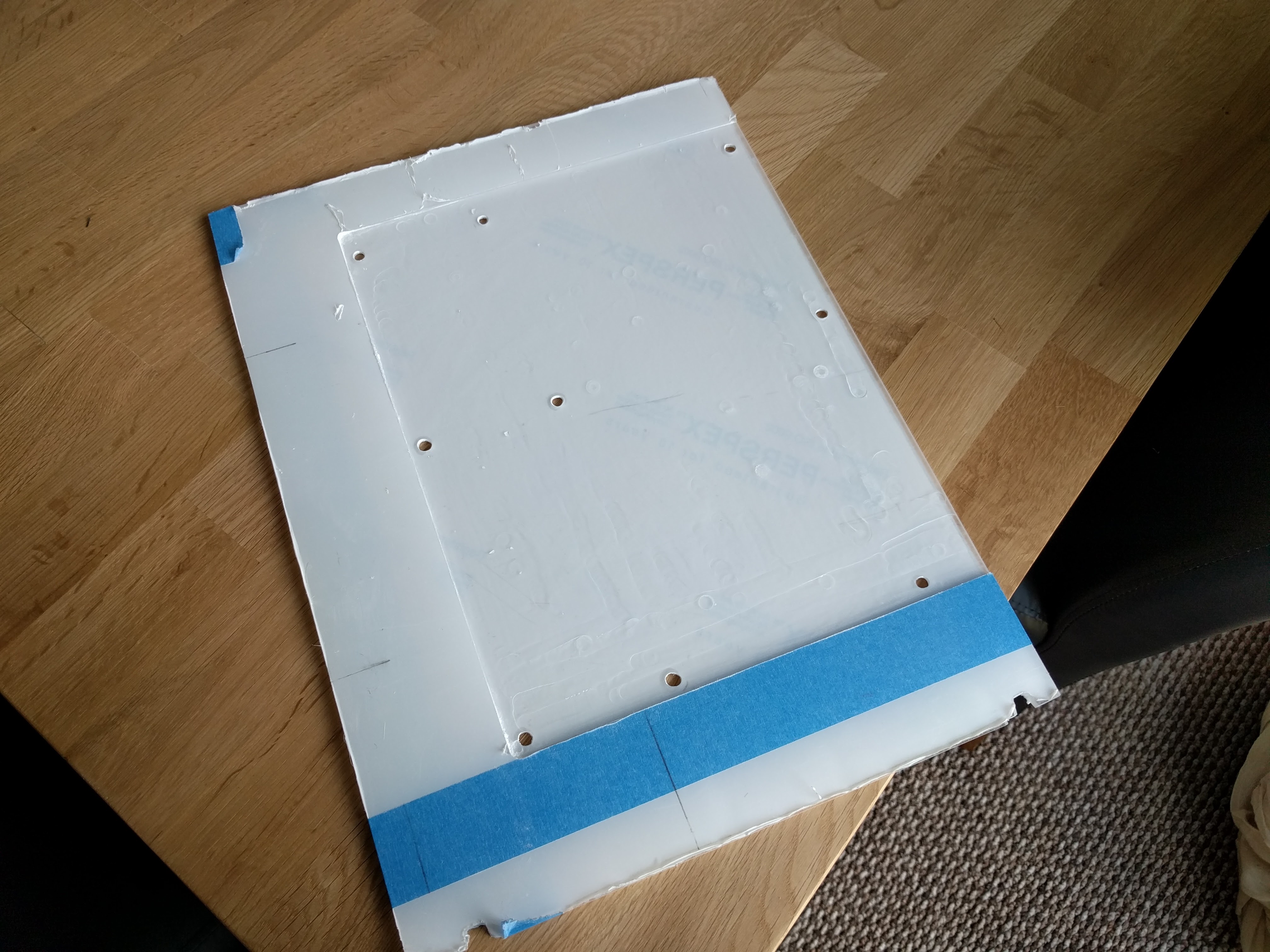
Thankfully I was able to prevent any mistakes and routed out the perfect recess for the motherboard. This is shown below with the final recess and a test mounting with the motherboard.
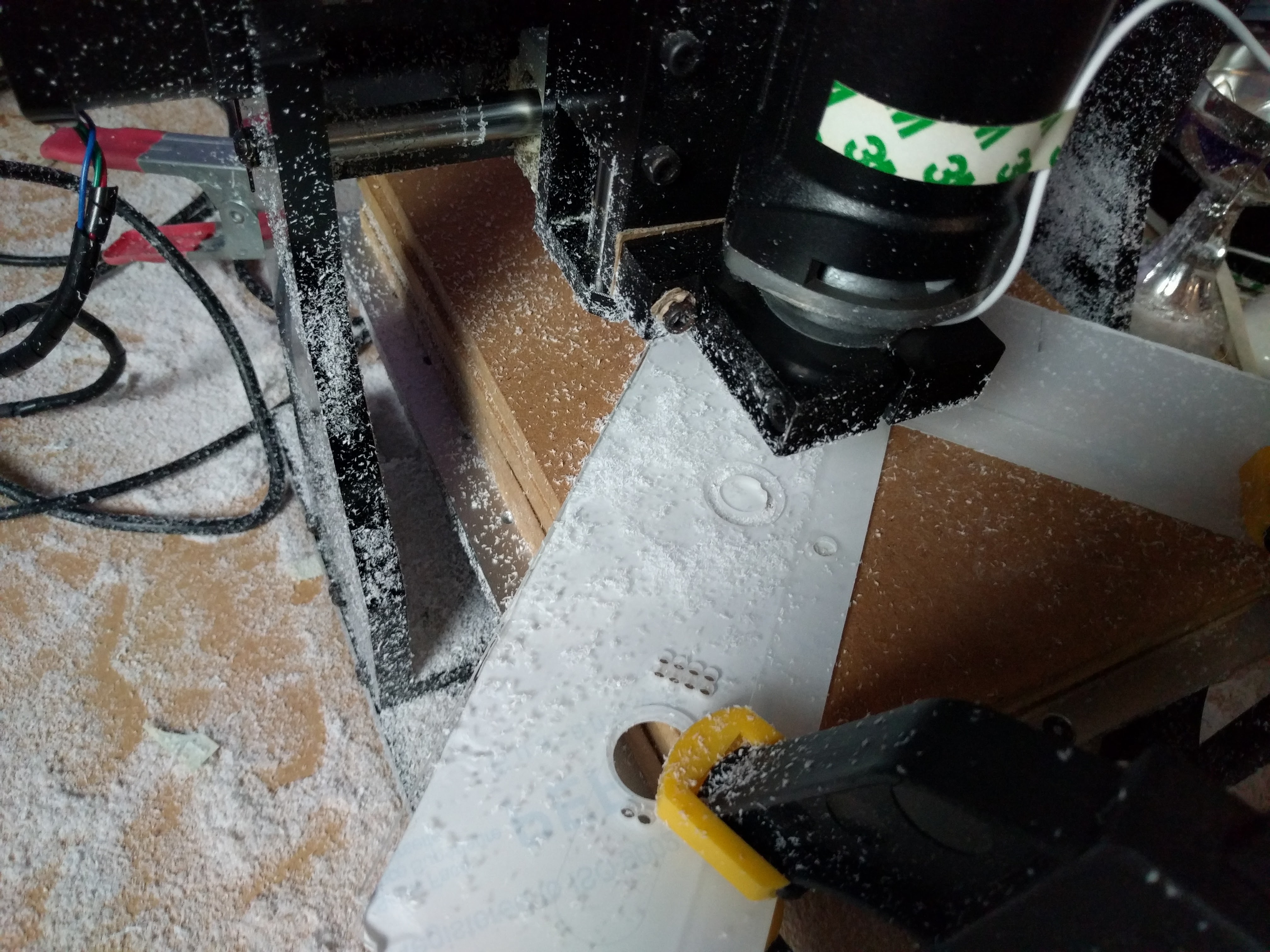
With the backboard fitting in the case nicely with the mother board mounted I now needed to work on the power and water passthroughs. I wanted to make as little modification to the case as possible so this meant that I didn’t want to be drilling new holes in the case however working with the holes that were already present. This worked out fine with me being able to place the power and water passthroughs in perfectly. I also wanted every single cable and water pipe to have its own passthrough in order to make the build look very clean, in order to get the precision and finish I wanted this meant that I had to use the CNC machine. This posed a challenge as the whole piece couldn’t fit in the machine. I did however manage to modify the tool paths and rotate the piece so that these small cuts could be made. This tomfoolery is shown below.
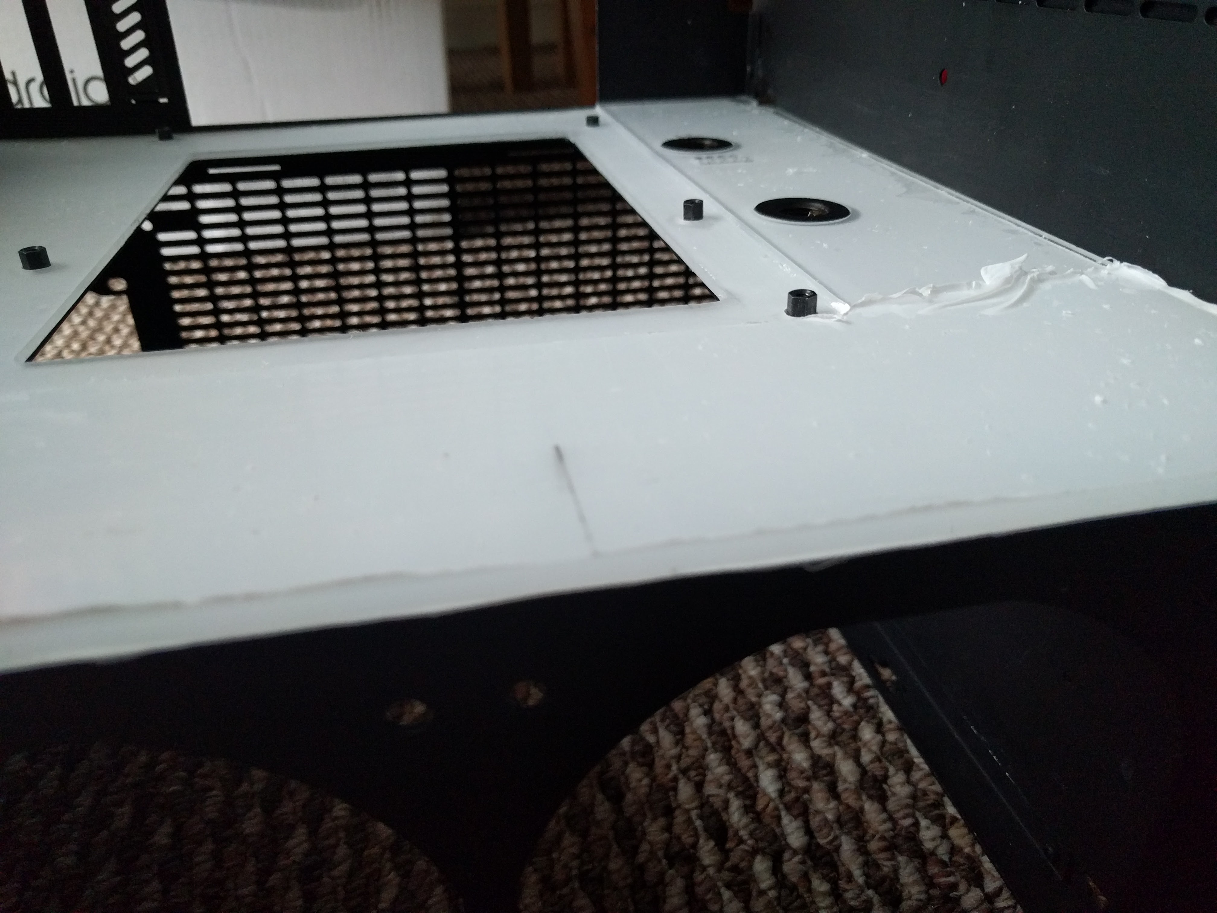
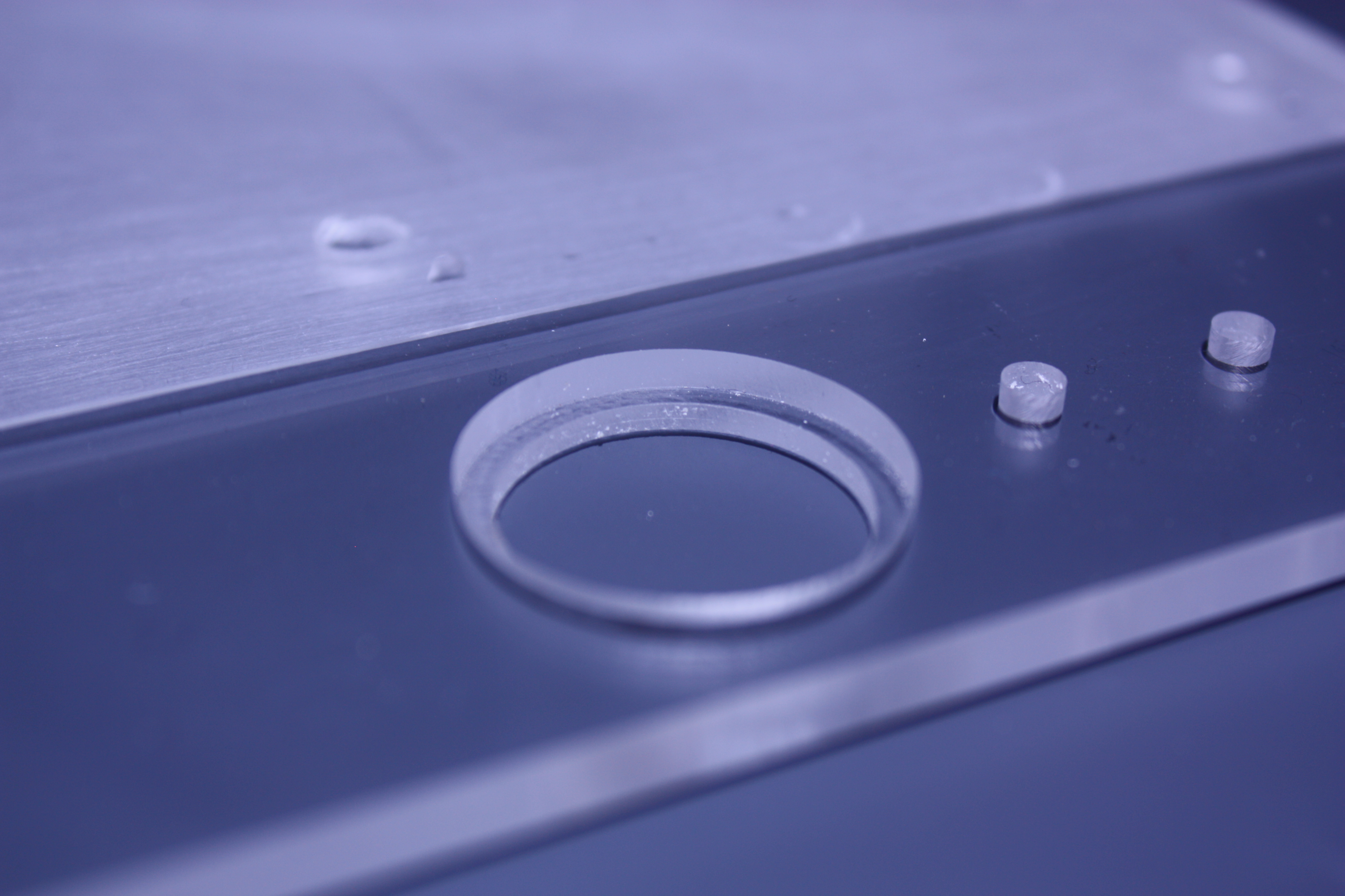
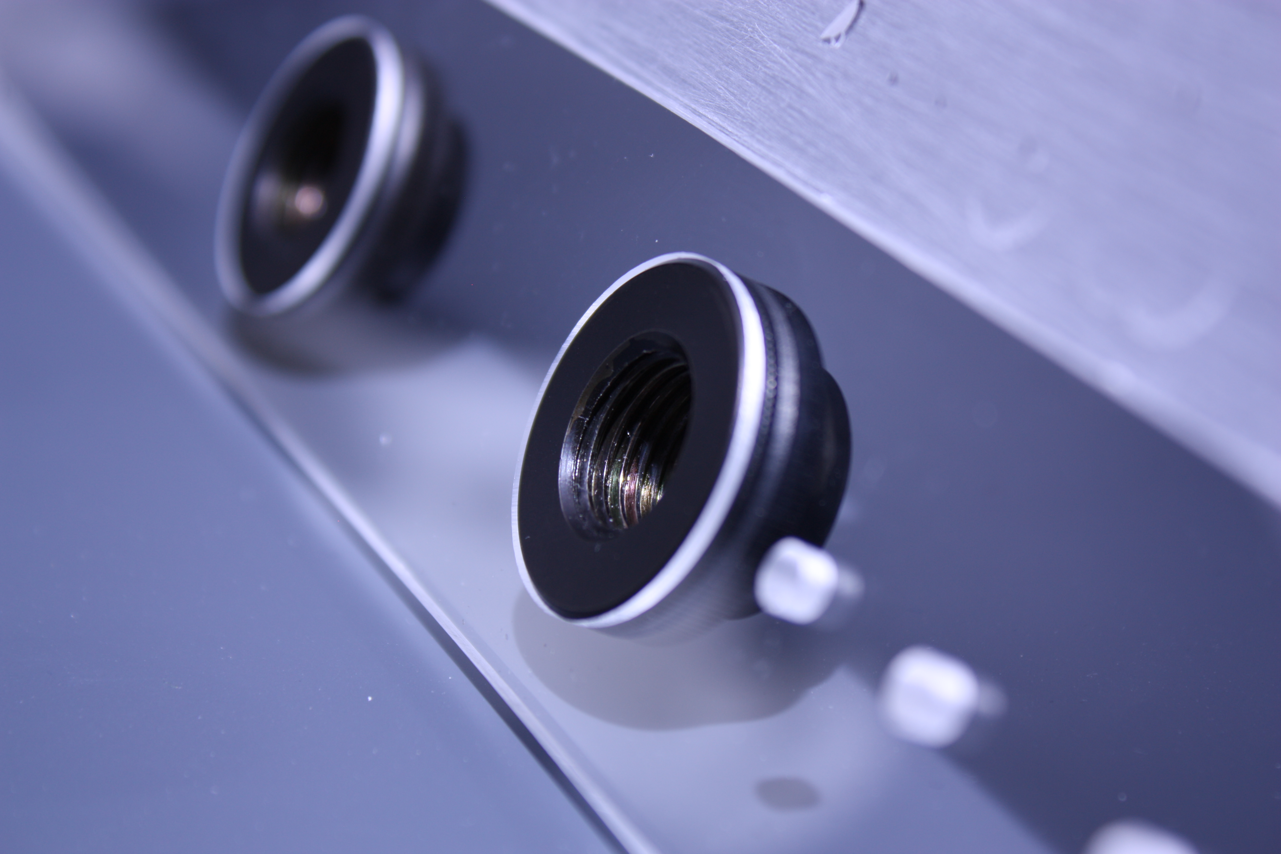
However difficult this was it was worth the effort as the results where perfect with the water passthroughs sitting perfectly flush and the cable passthroughs being cut without a single error.
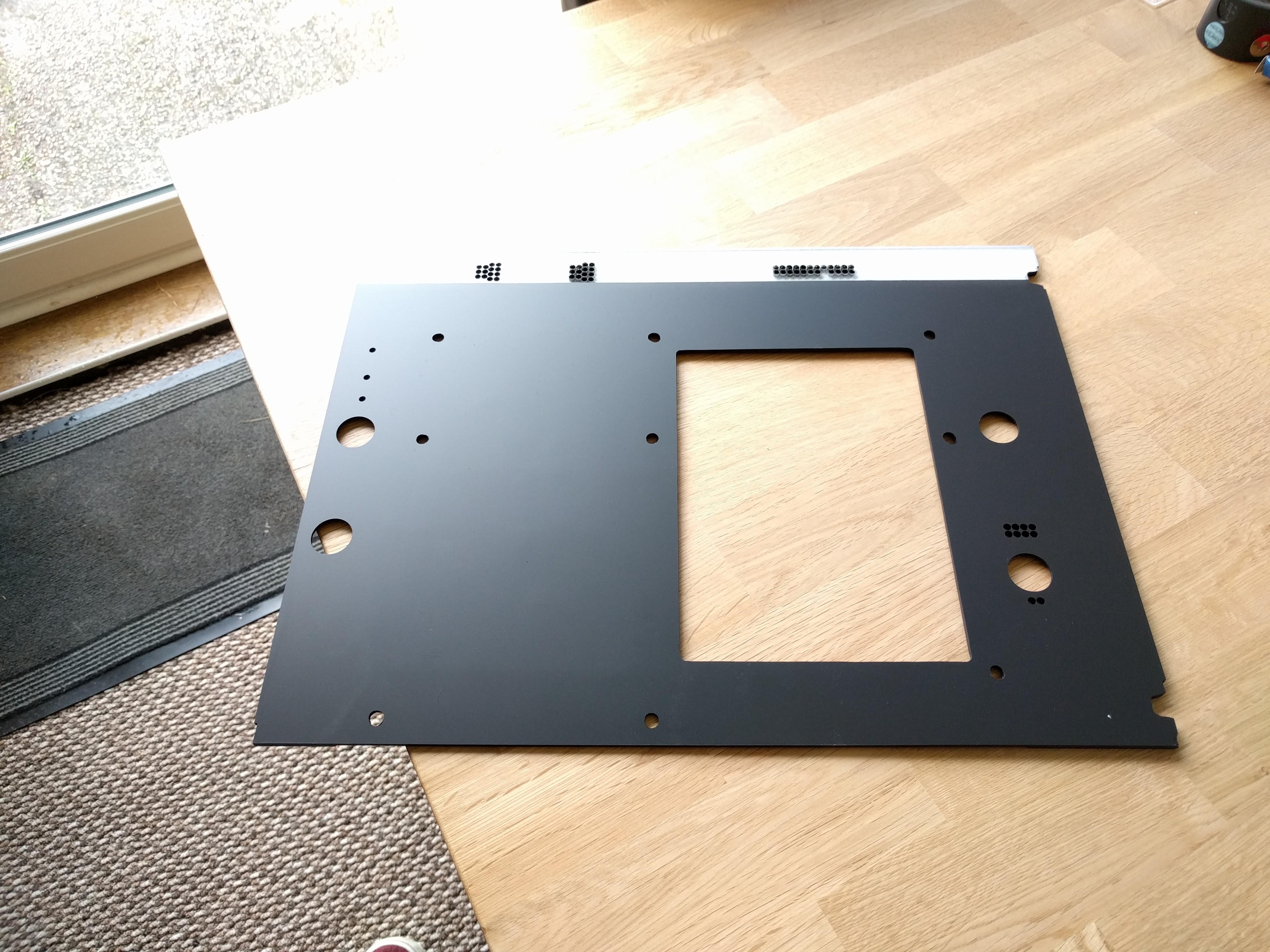
This then had to be repeated for all of the passthroughs necessary, including the 24pin power and the GPU power cables. The final piece pre-paint is shown below:
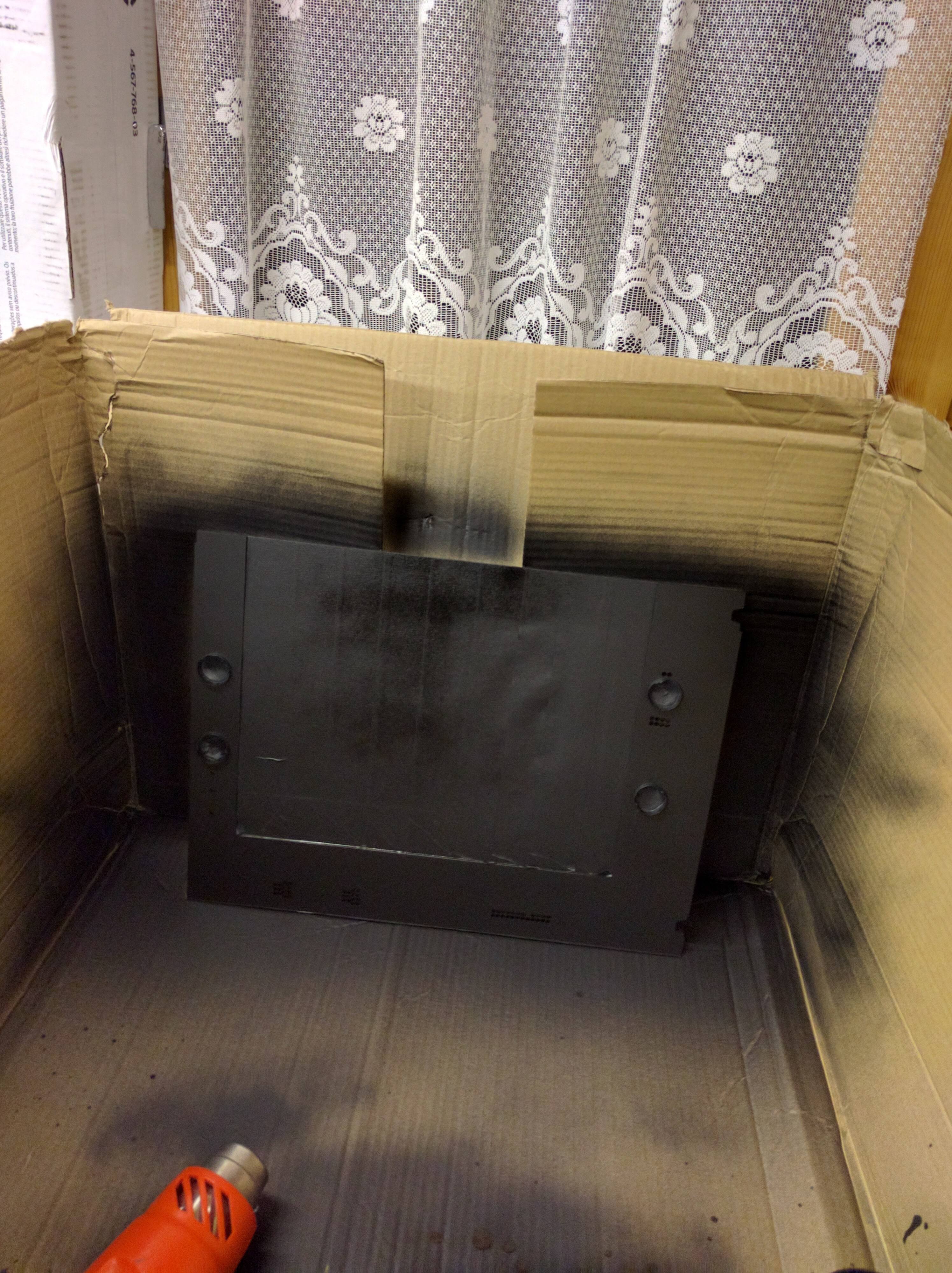
This was then first painted white and then finally matte black to match the case.
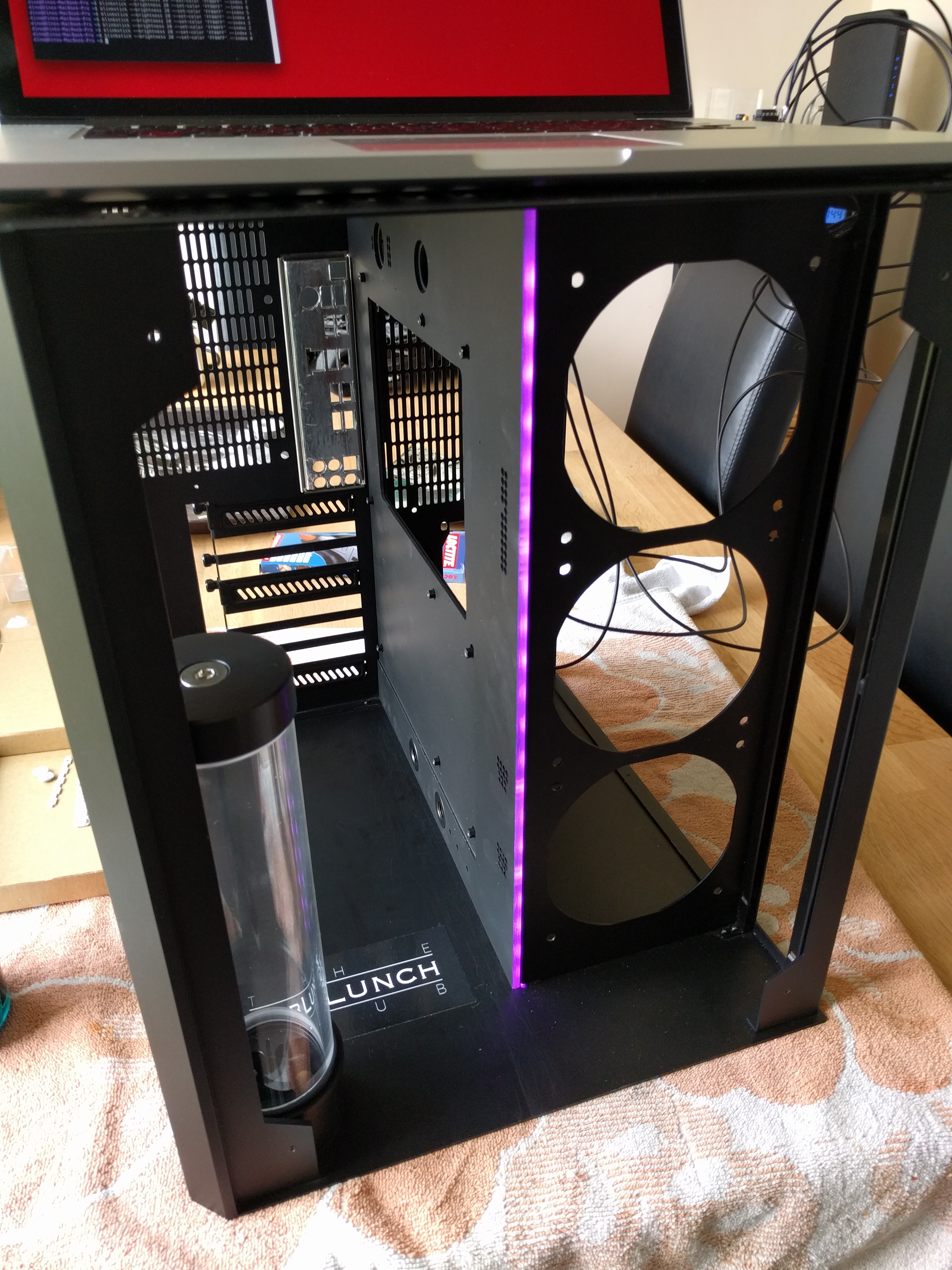
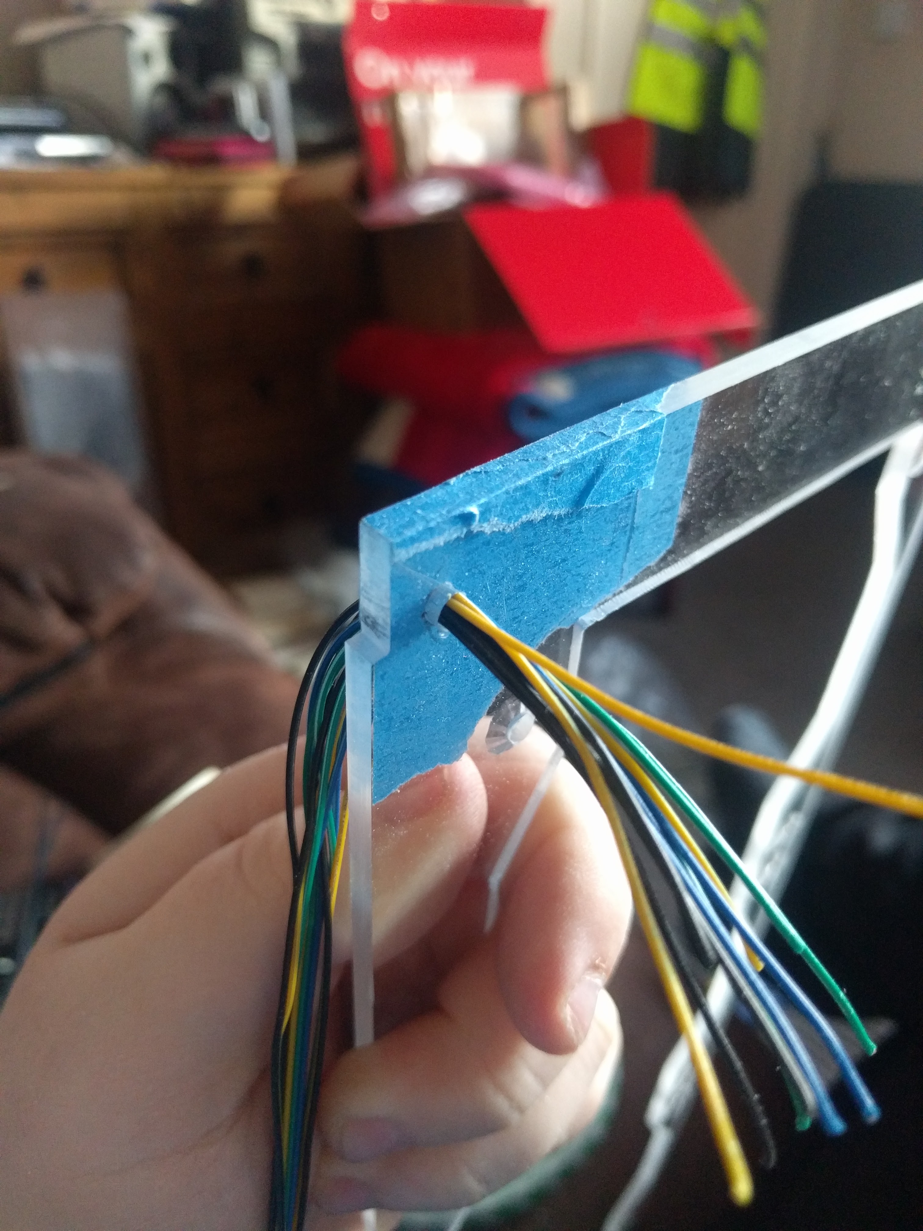
The reason for first painting it white and then matte black was due to the fact I left the leading edge transparent allowing for addressable LEDs to be mounted along the edge. The first white coat would aid in maintaining brightness for the side firing LEDs in order to create a custom loading or progress bar along the edge. Below you can see the transparent edge that was left and a test of the LEDs.
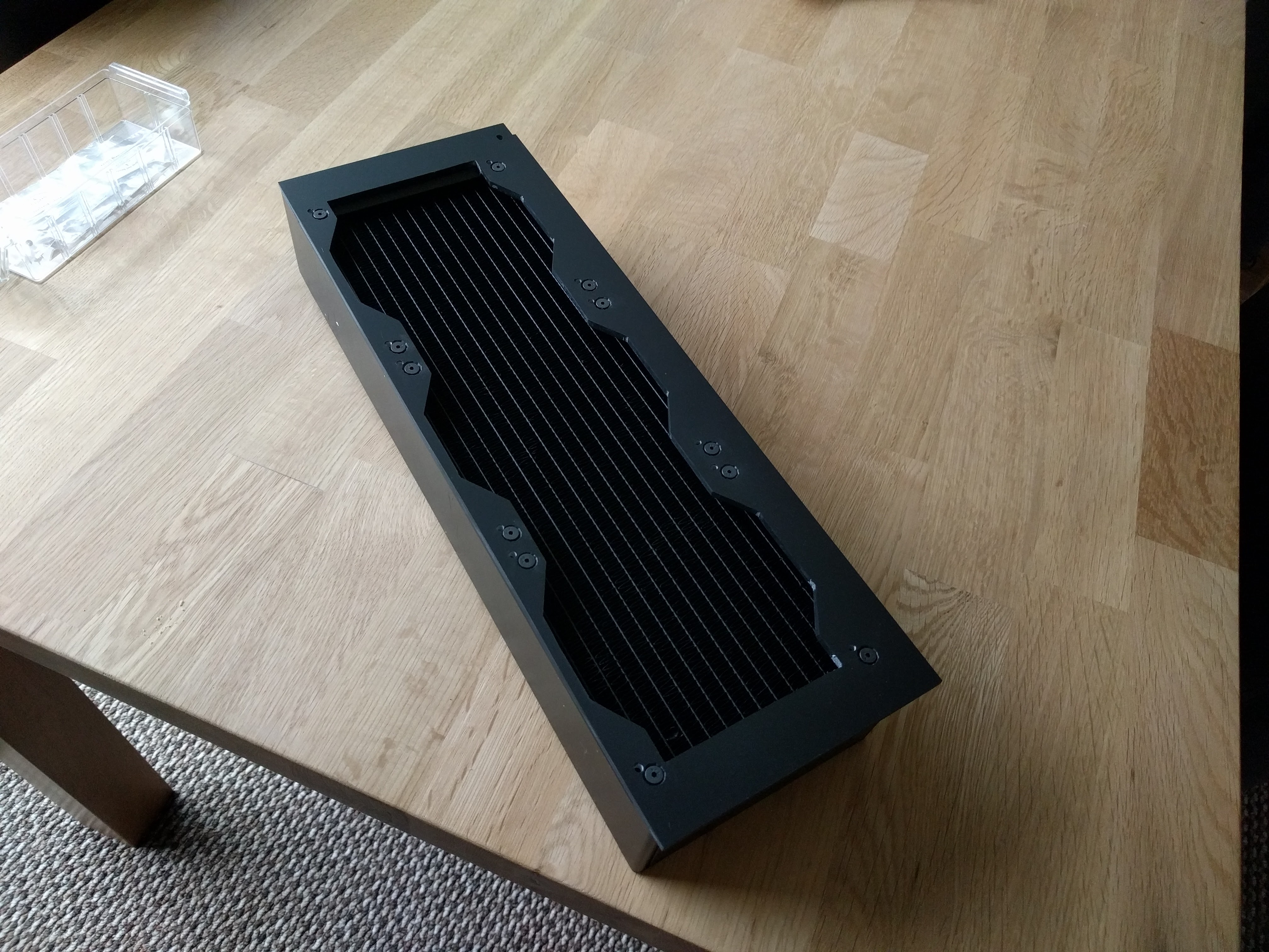
Radiator Mount
The final part that needed to be made was a mount for the triple radiator. This was relatively easy to do as it just needed to mount the rad with enough room to accommodate the LEDs behind and a passthrough for the triple fans in the front of the PC.
Sleeving All Power Cables
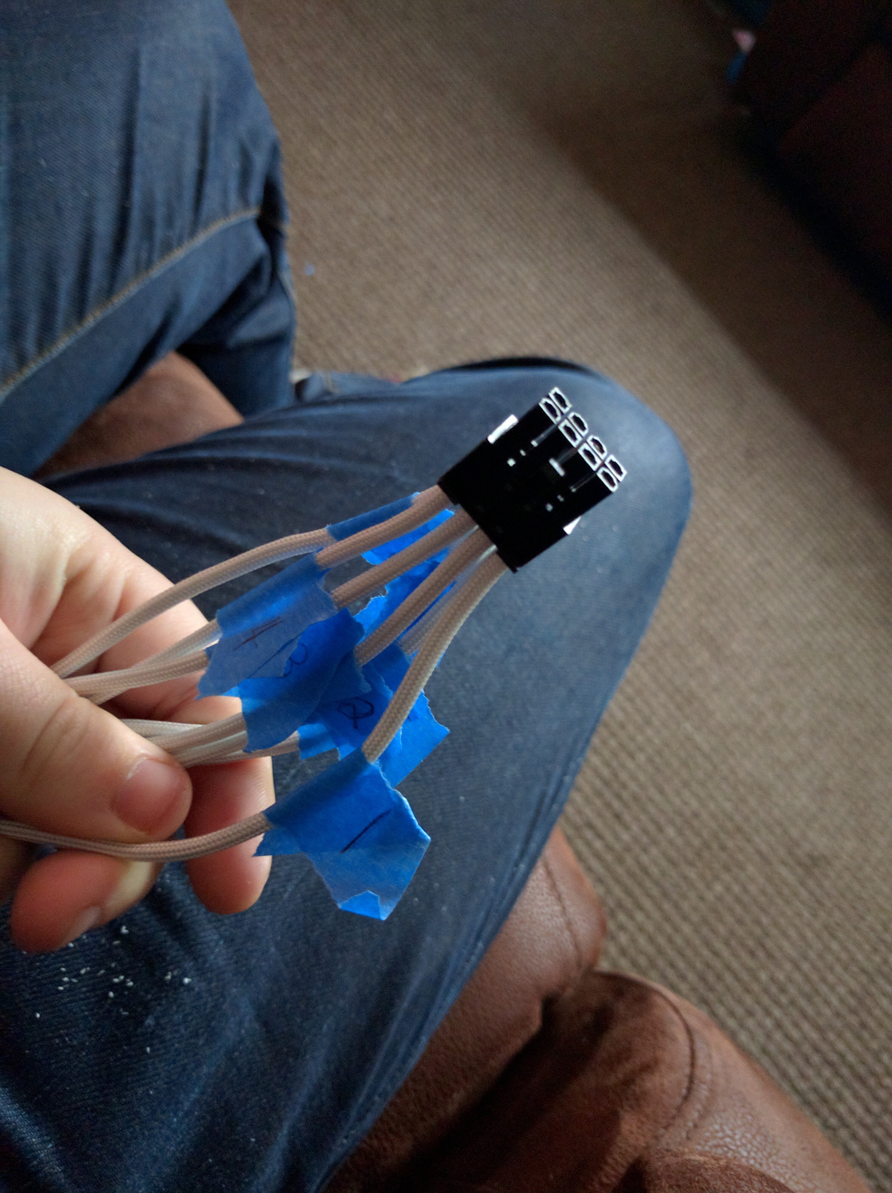
Now we mainly move onto the assembly, but first I had to manually sleeve all the power cables that would be used. This was needed for a couple of reasons, firstly off the shelf individually sleeved cables where very rare and expensive at this point in time, and they where limited by the finishes and colours available. Instead I used a trick that many did at the time and bought a bunch of paracord that could be de-sleeved and the outer fabric used as power cable sleeve. I ordered a bunch of white and black paracord and begun sleeving every cable. When doing this it is important to make sure that all cables are returned to the correct pins within their connectors.
I also had to make some custom Y connectors that I made sure where finished well to give a professional appearance. These where often needed for fan connections and the like.
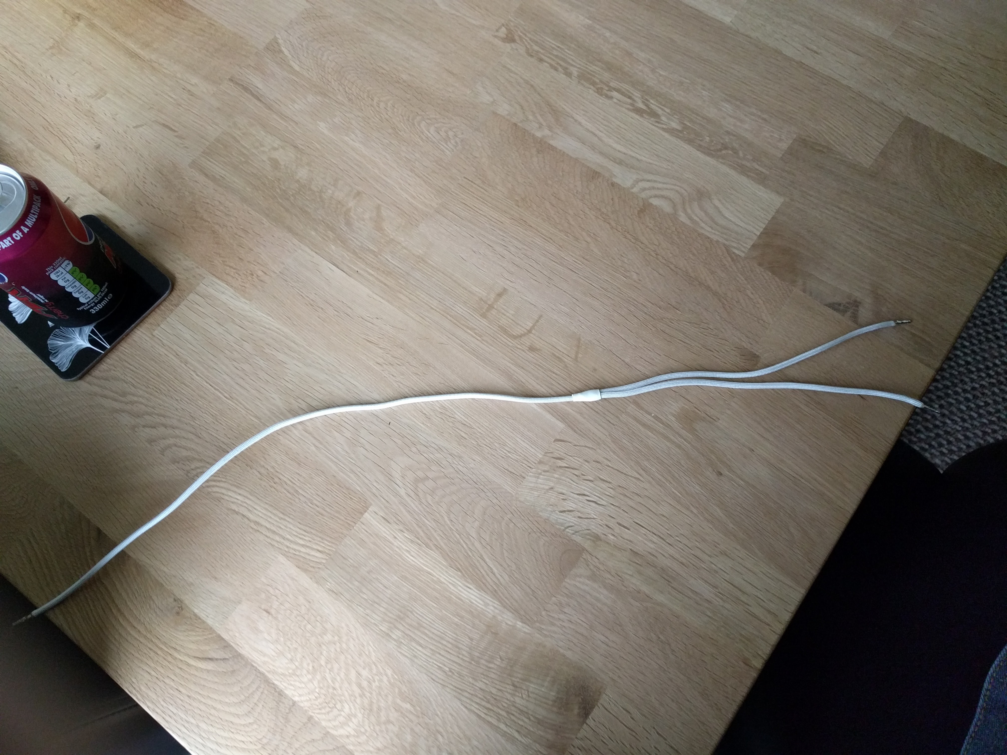
I also went to the trouble of making the fan cables the prefect length so they could be routed nicely and also custom sleeving those as well below I show the sleeving of the fan cables in white, however I did not like the look once I had finished so had to go back and re-sleeving them in black for the final build.
Final Build
We now move onto the final build of the computer that involved putting all the components together and finishing off all of the little final 1% bits that make the final build high-quality.
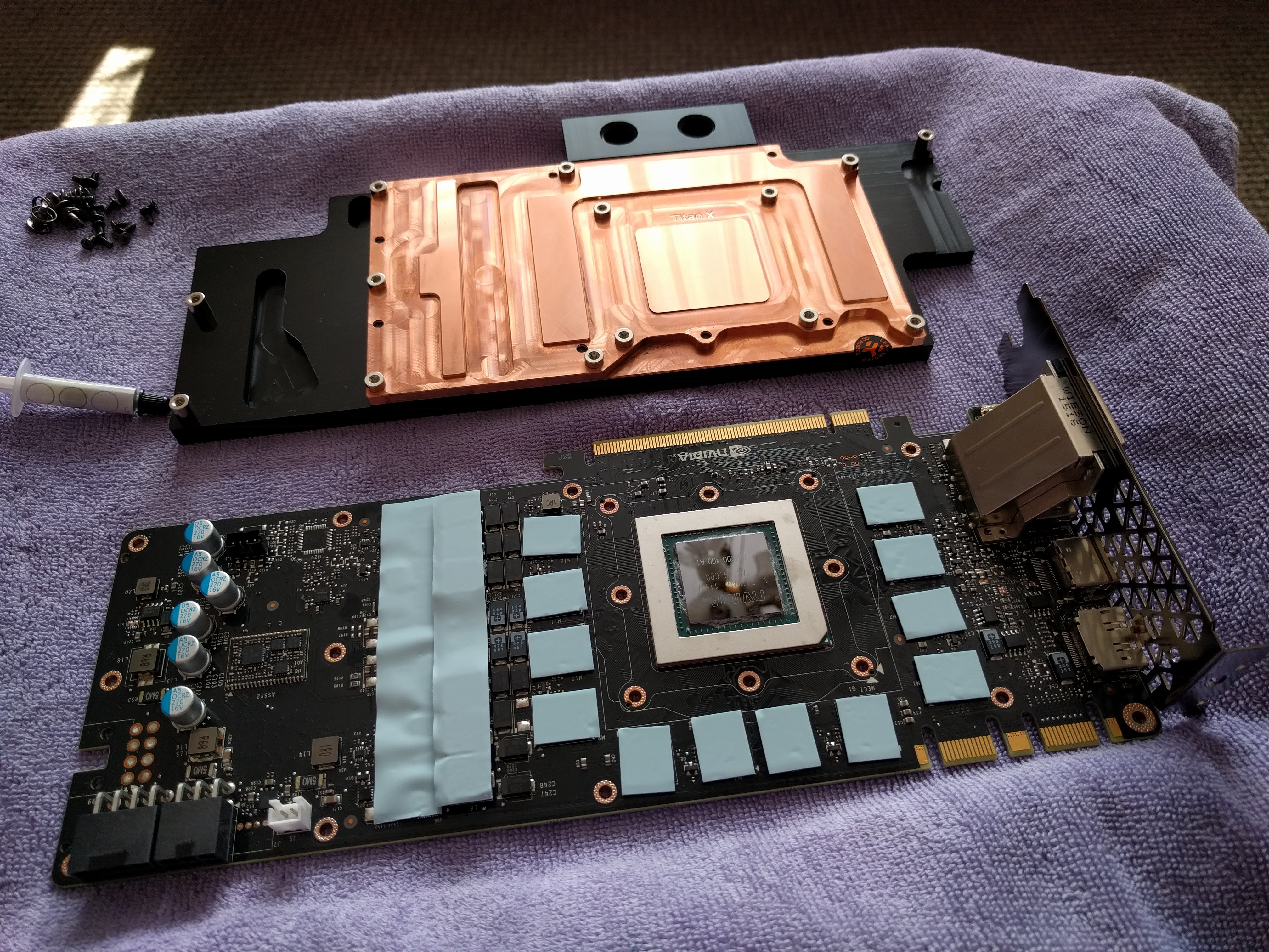
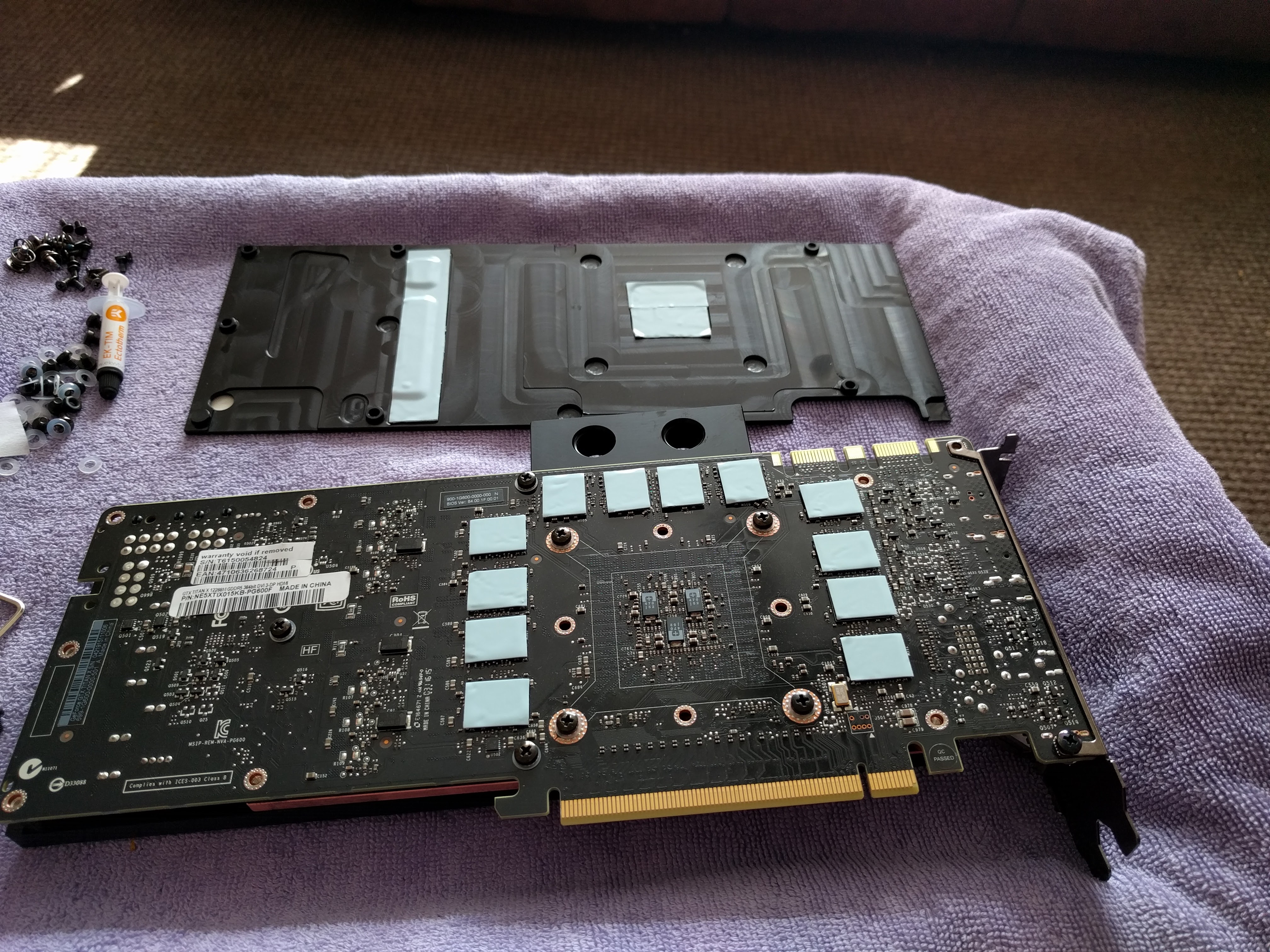
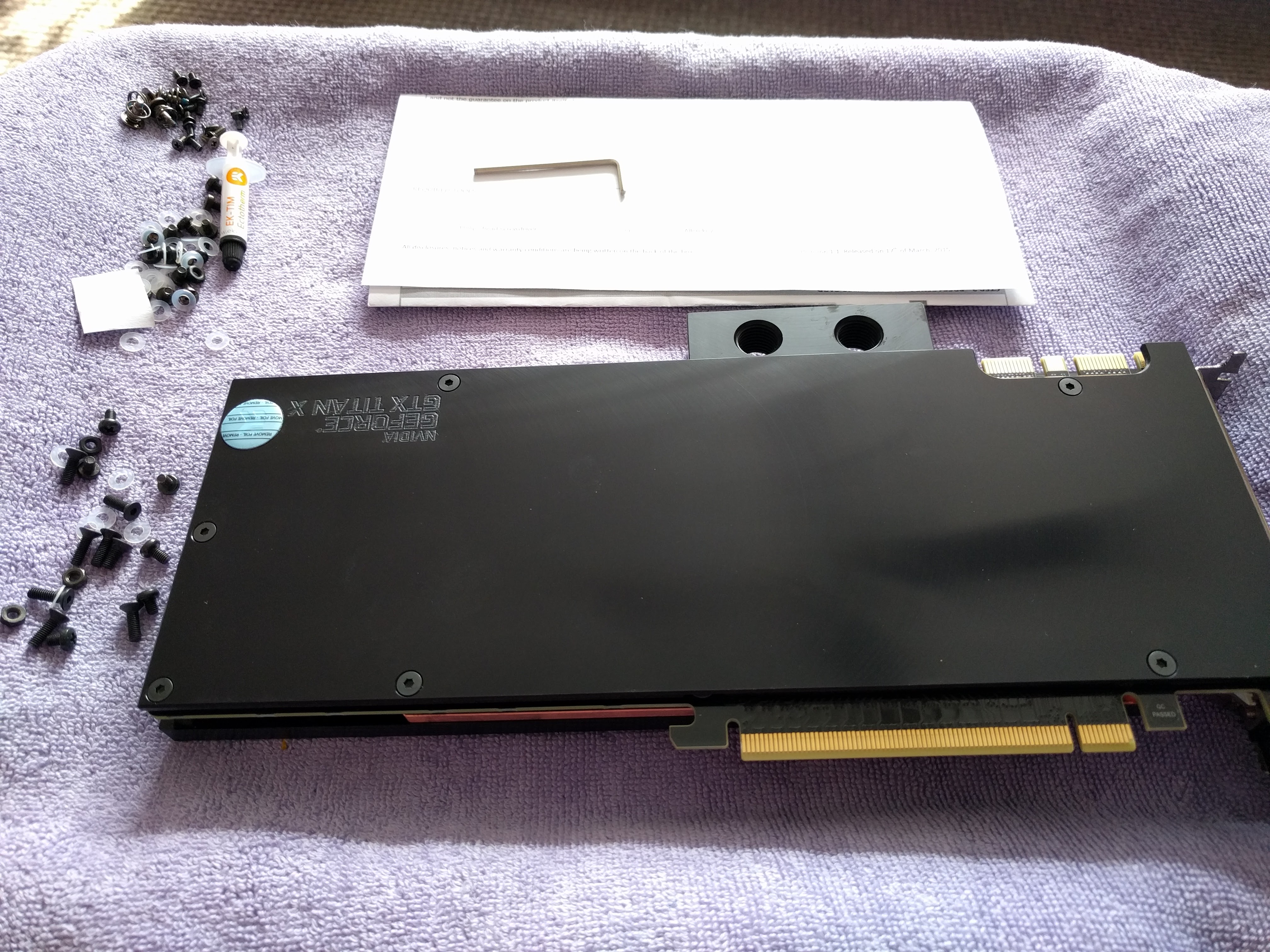
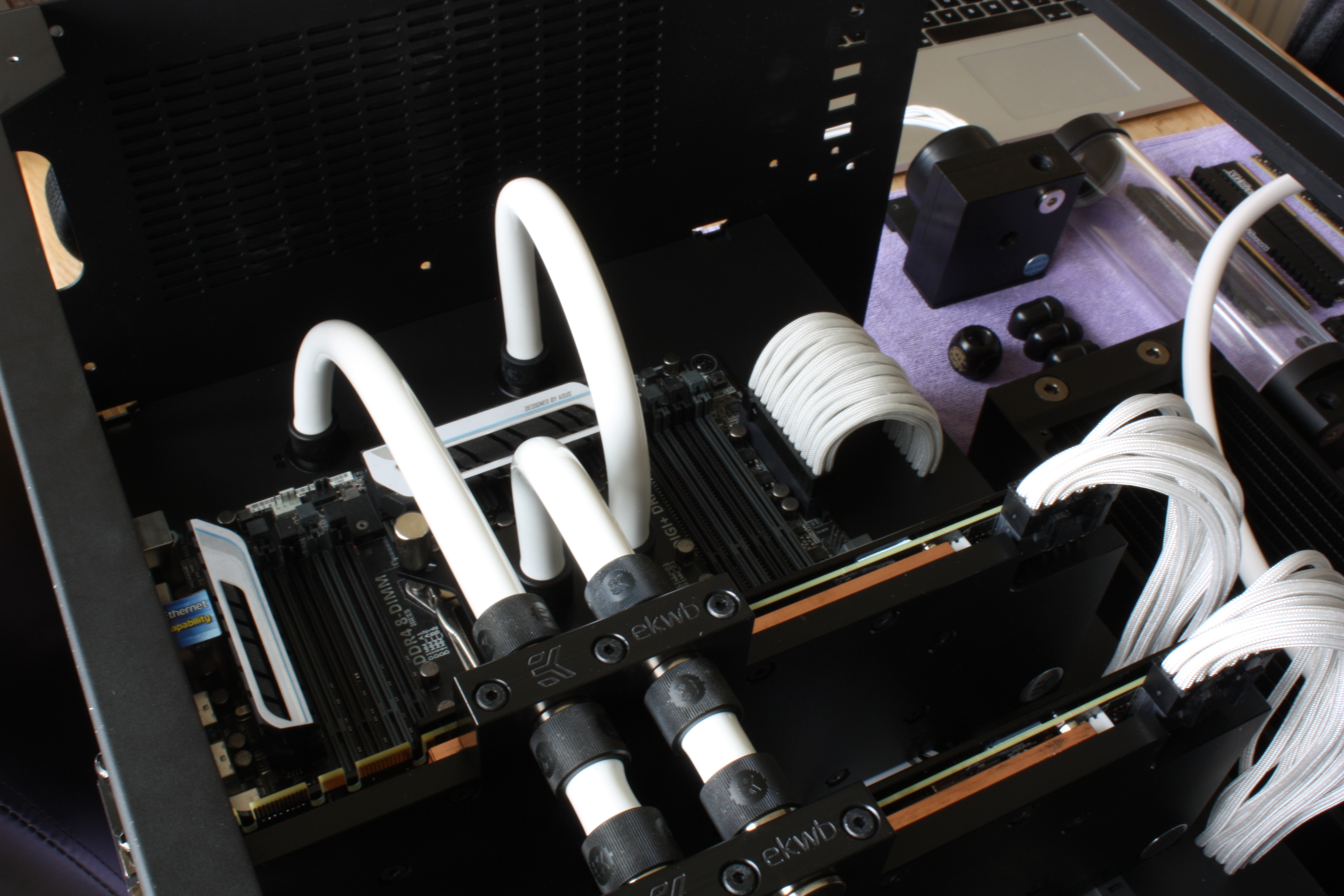
The first thing to tackle was installing the waterblocks on the Titan GPUs.
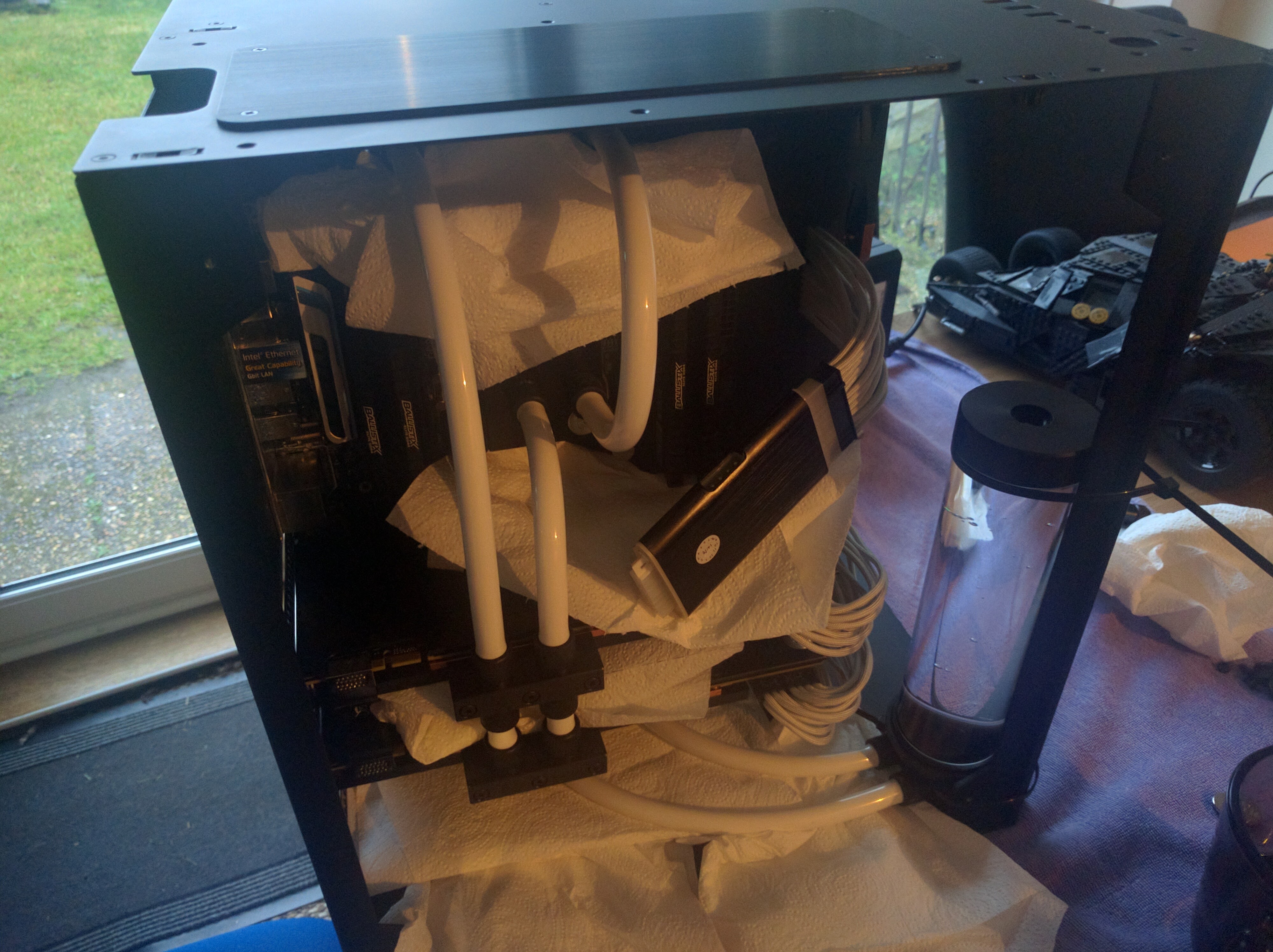
Once this was done it was time for the final assembly of the computer complete with all water components in order to add water and do a leak test. Before the leak test I had to route all of the power cable individually through their respective cutouts, shown below is one of the GPU power connectors being fed through with the connector having to be reattached and connected to the GPUs.
All of the components would then need to be plumed into the water loop in order to conduct the leak test. These components sans the CPU block are shown below.
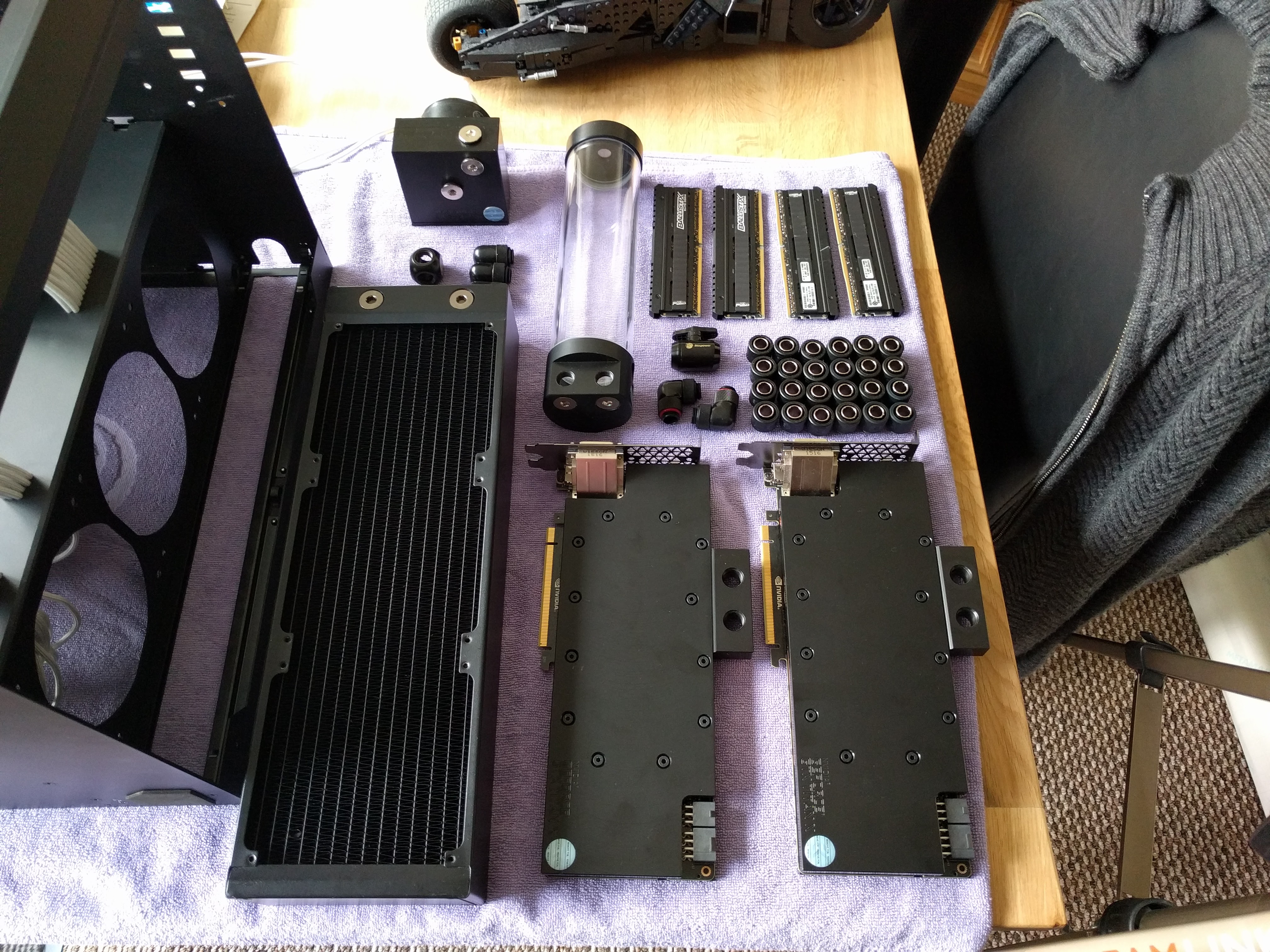
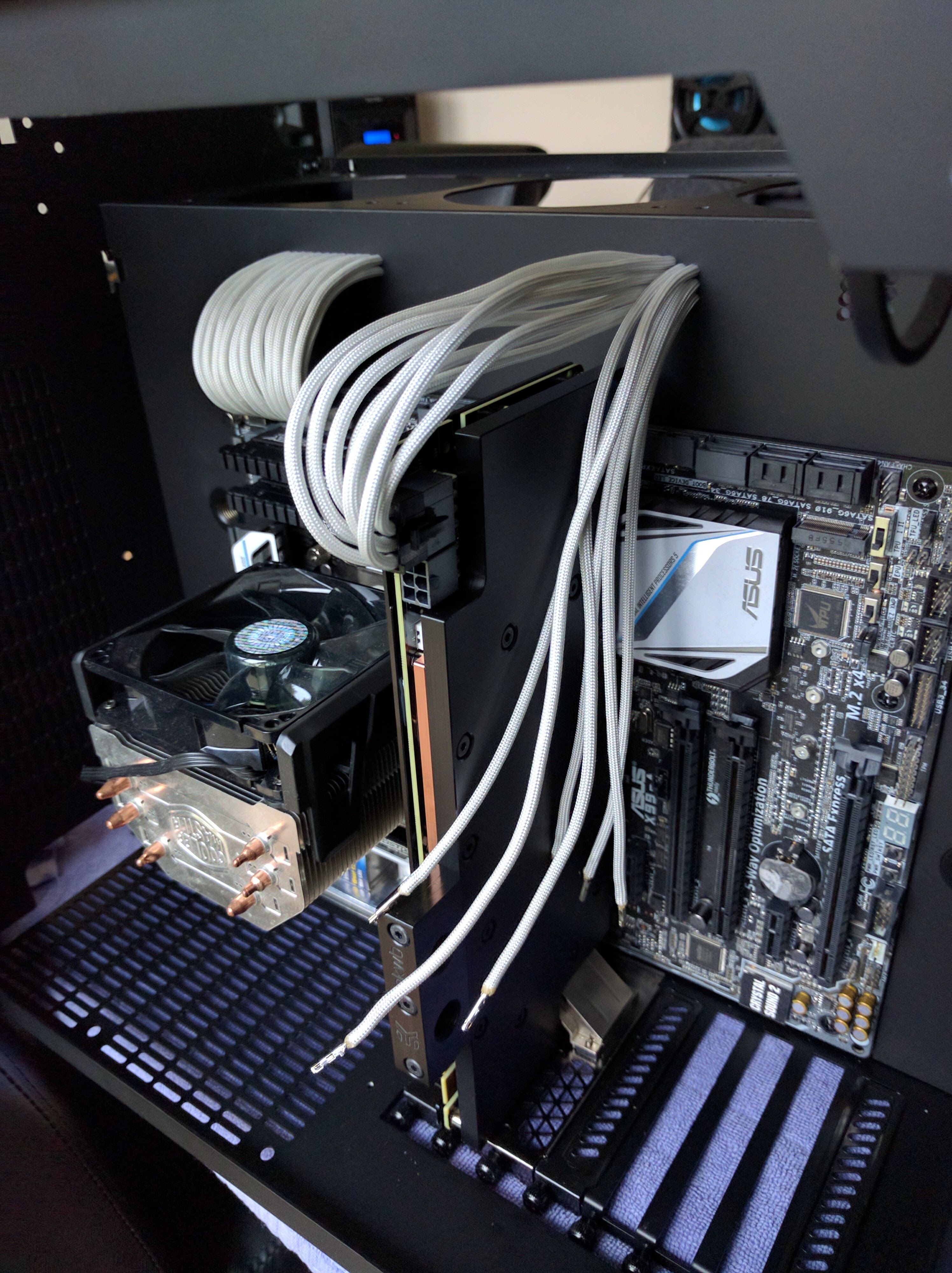
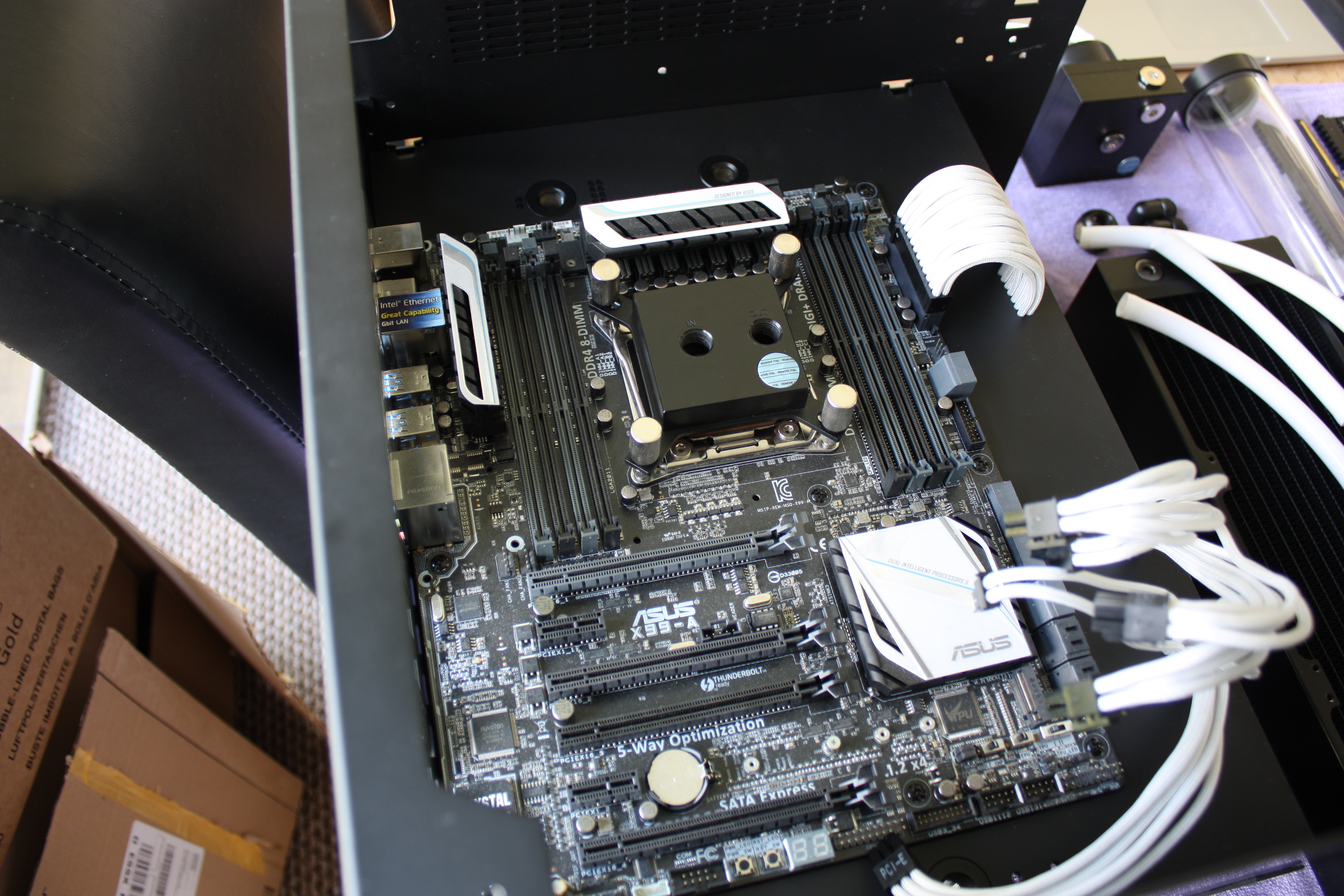
First I removed the temporary air cooler, as it would get in the way for the rest of the build, and installed the CPU water block. This would be downstream of the water flow to the GPUs.
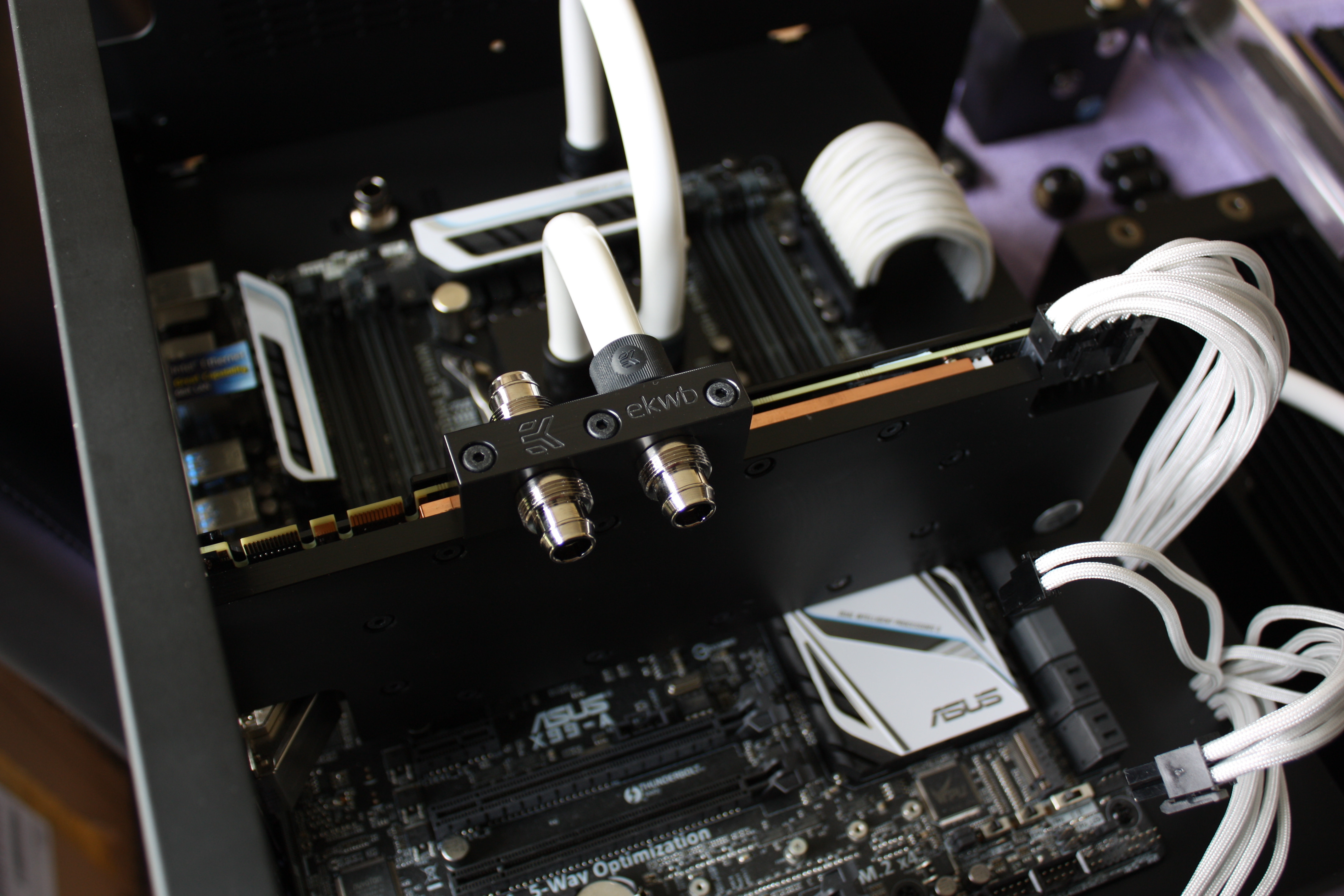
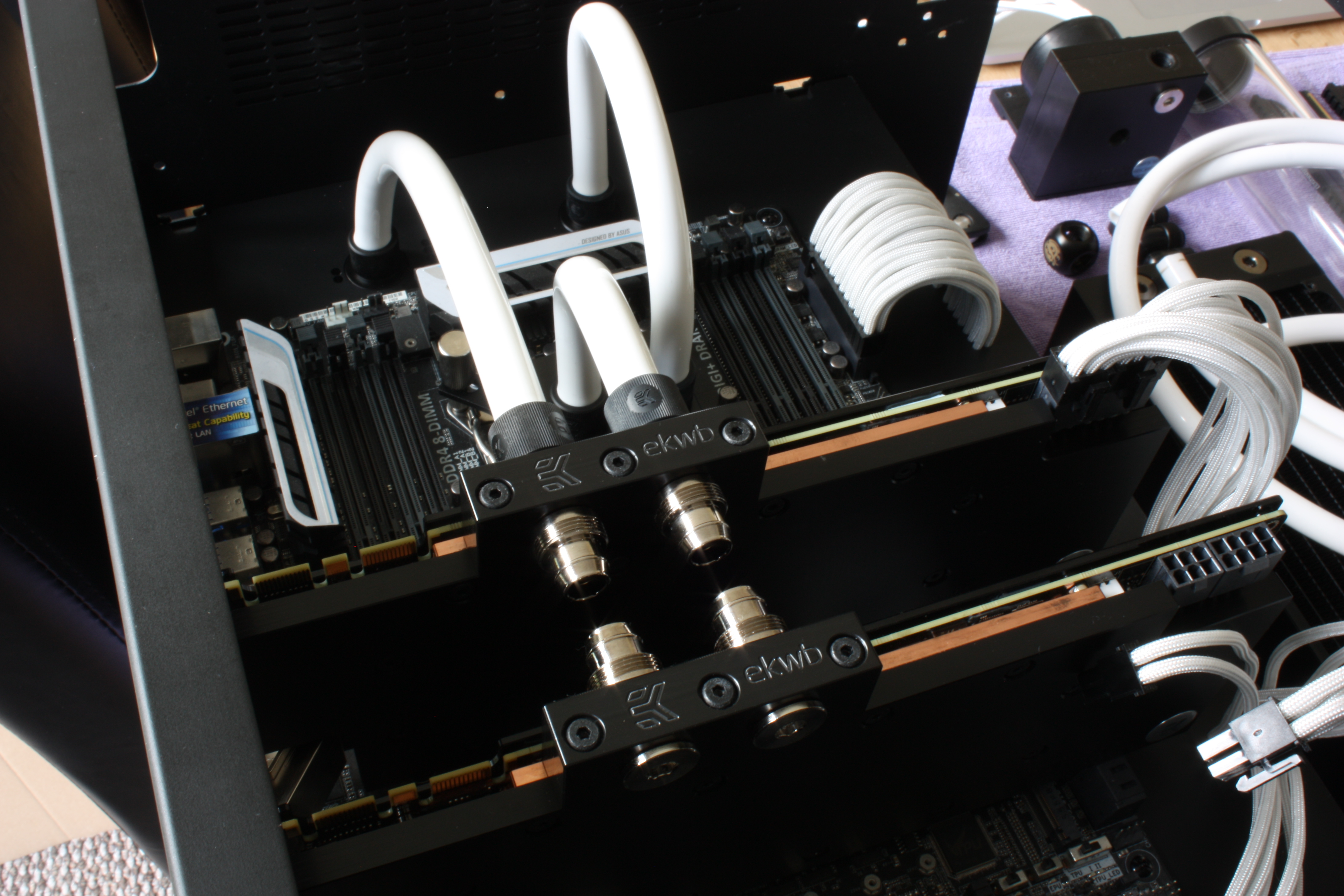
I then installed the GPUs into the machine and begun adding the water pipe for routing of the water to all of the components. The GPUs where plumed in parallel as the upstream components and then the output fed to the CPU. I knew ahead of time that this machine was mainly for deep learning experiments so cooling of the GPUs was the priority, hence having them be the first components in the loop, with cooling of the CPU being a secondary consideration. This probably doesn’t actually make any difference on the temperatures due to the flow rate but it seemed like the most logical setup to me.
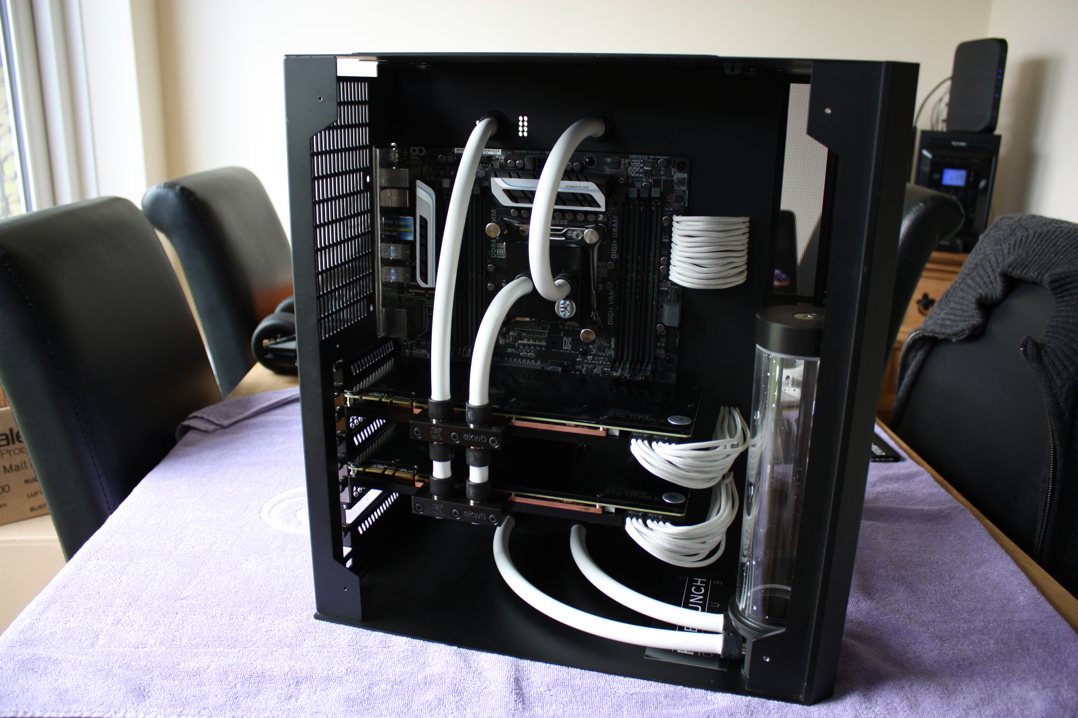
Once the GPUs where installed the reservoir, the final component in the front of the PC, could be added and plumed in. In the picture below you can see the front of the system basically complete.
Once the front was complete I still needed to plumb in the rear of the case. This included running the power cables and the water tubing as well as fitting the radiator and pump. Below you can see a snippet of the work done to plumb and connect the rear of the case together. Unfortunately I didn’t take as many pictures of this process.
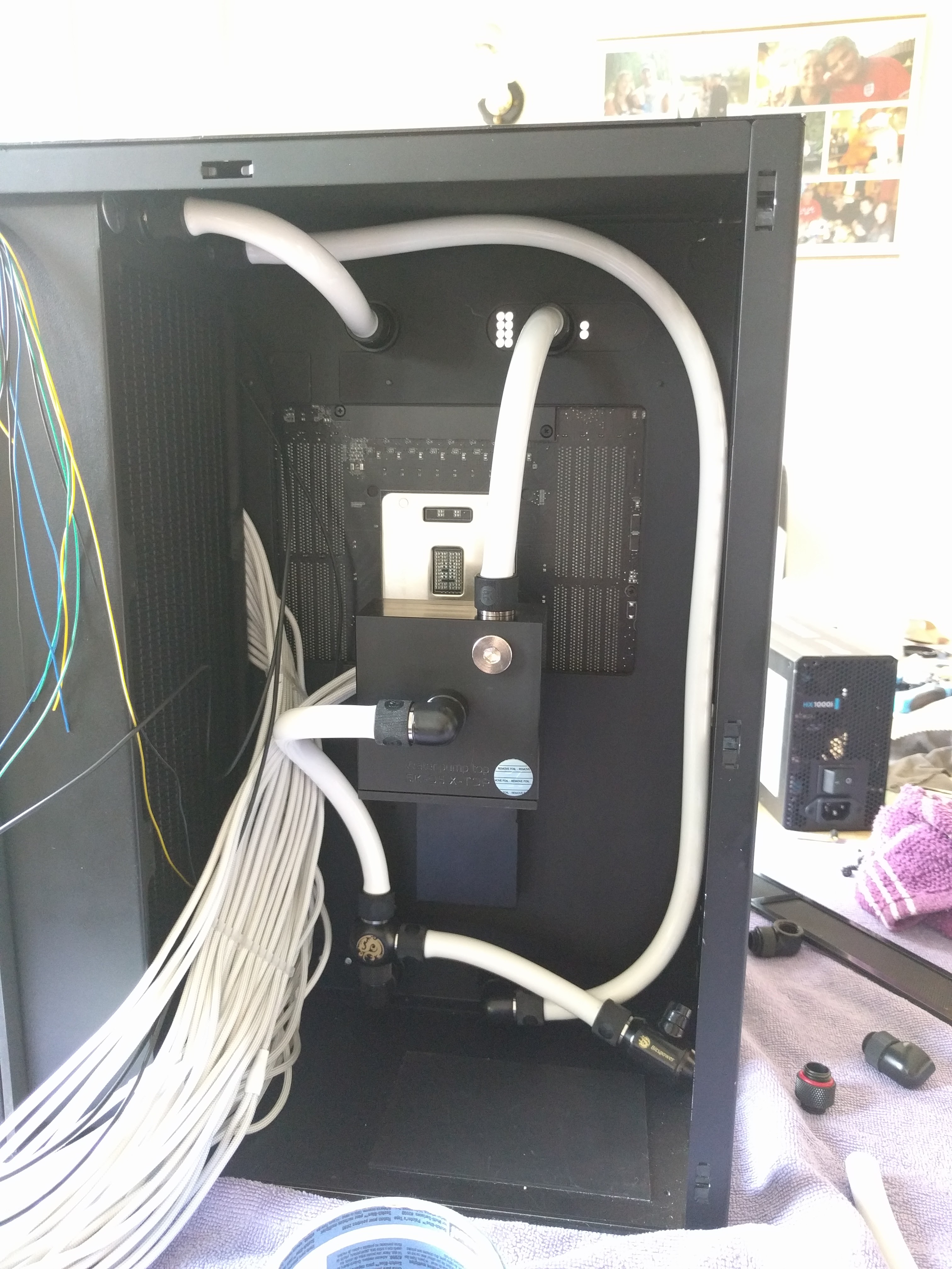
Once the rear was plumbed in I was able to conduct a water leak test by running the water pump without powering on any of the components in case their was a leak. I ended up having to only replace one faulty connector and then the water loop was completely done.
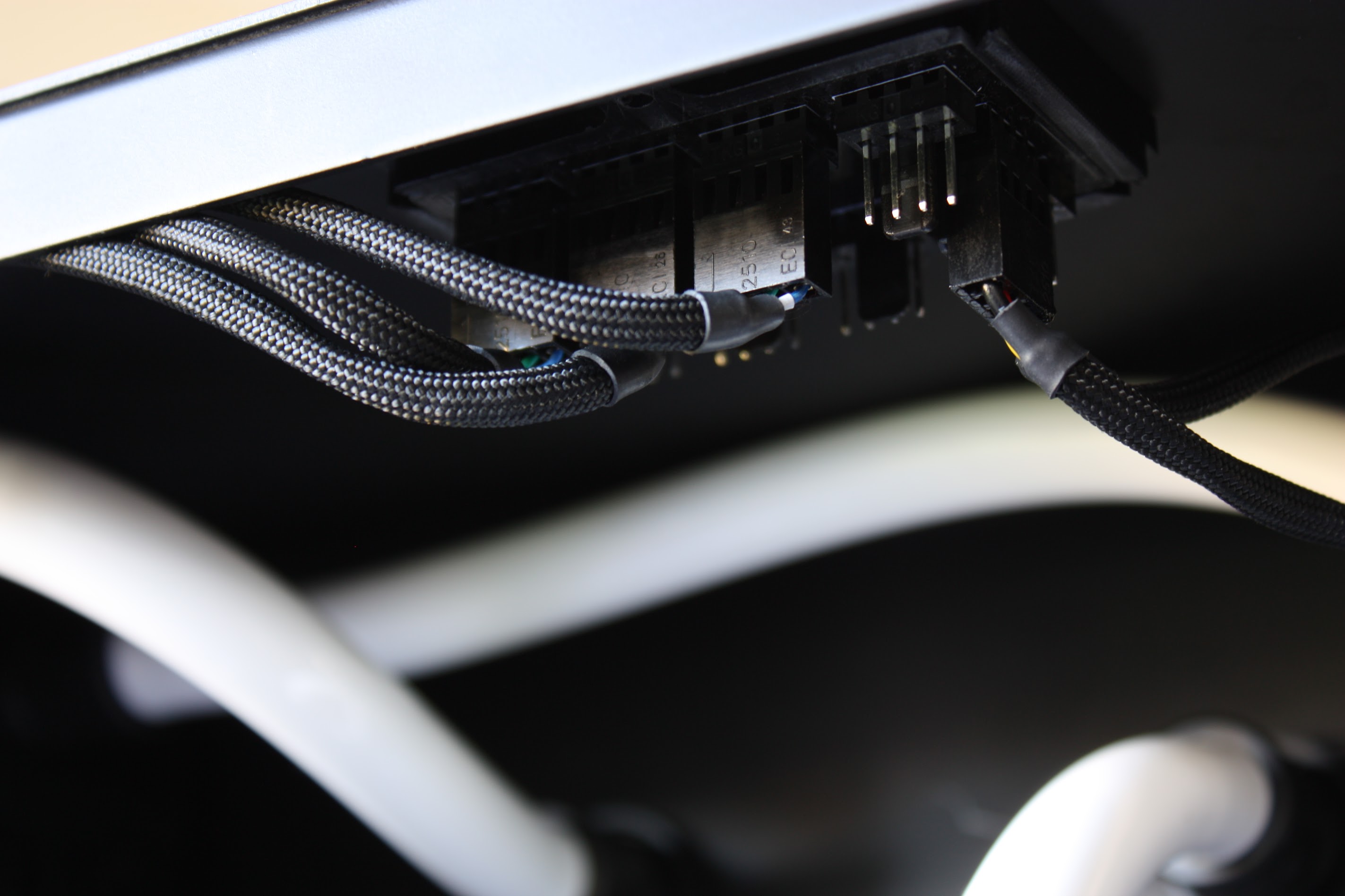
Unfortunately I didn’t get many pictures towards the end of this build, as I remember I believe that I had to start training some RL agents to play DOOM for a competition and couldn’t spend the time documenting with pictures the last part of the final assembly. However I will leave this last image of the fan splitter that terminates at the end of the custom length fan cables from the front of the case.
Conclusion
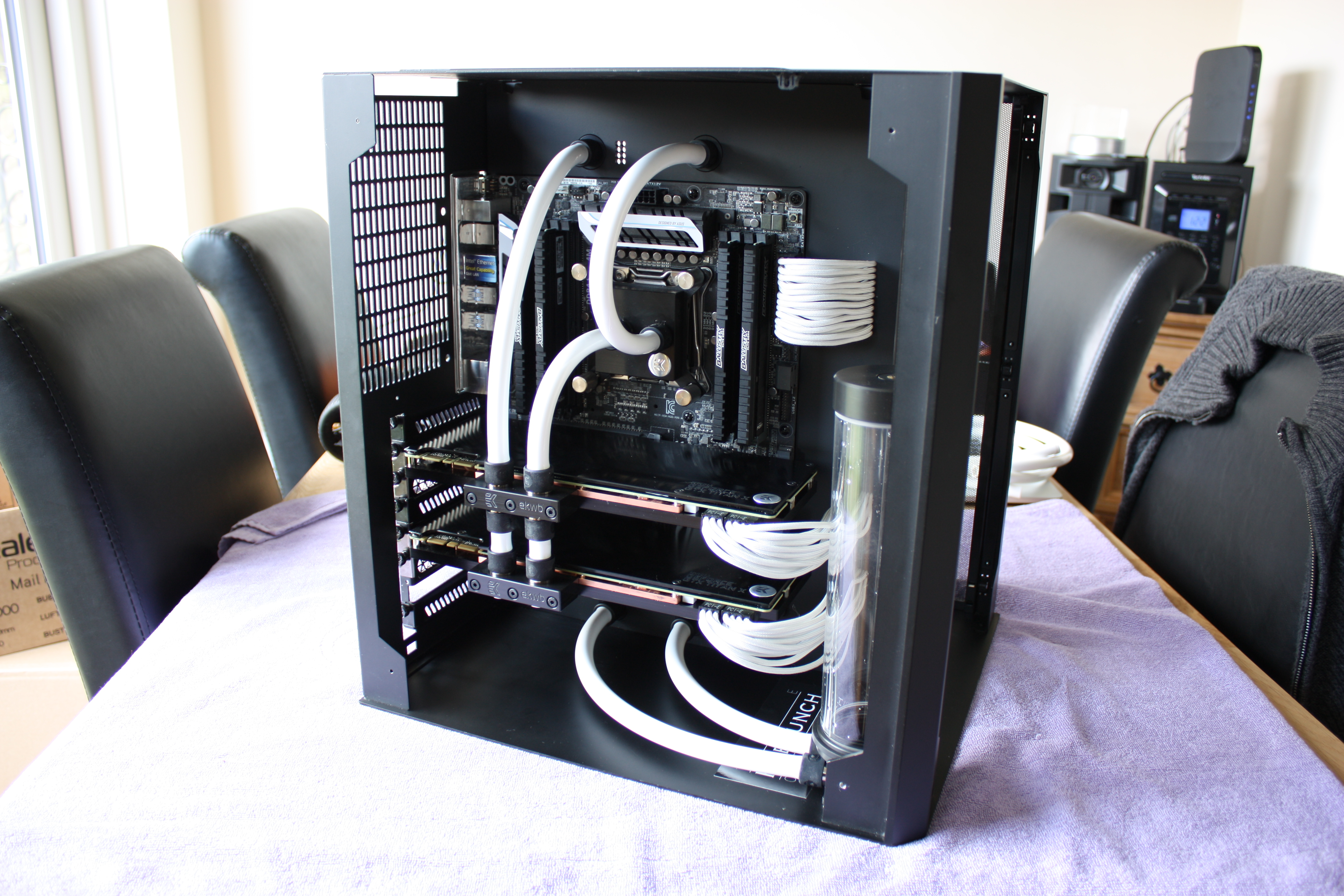
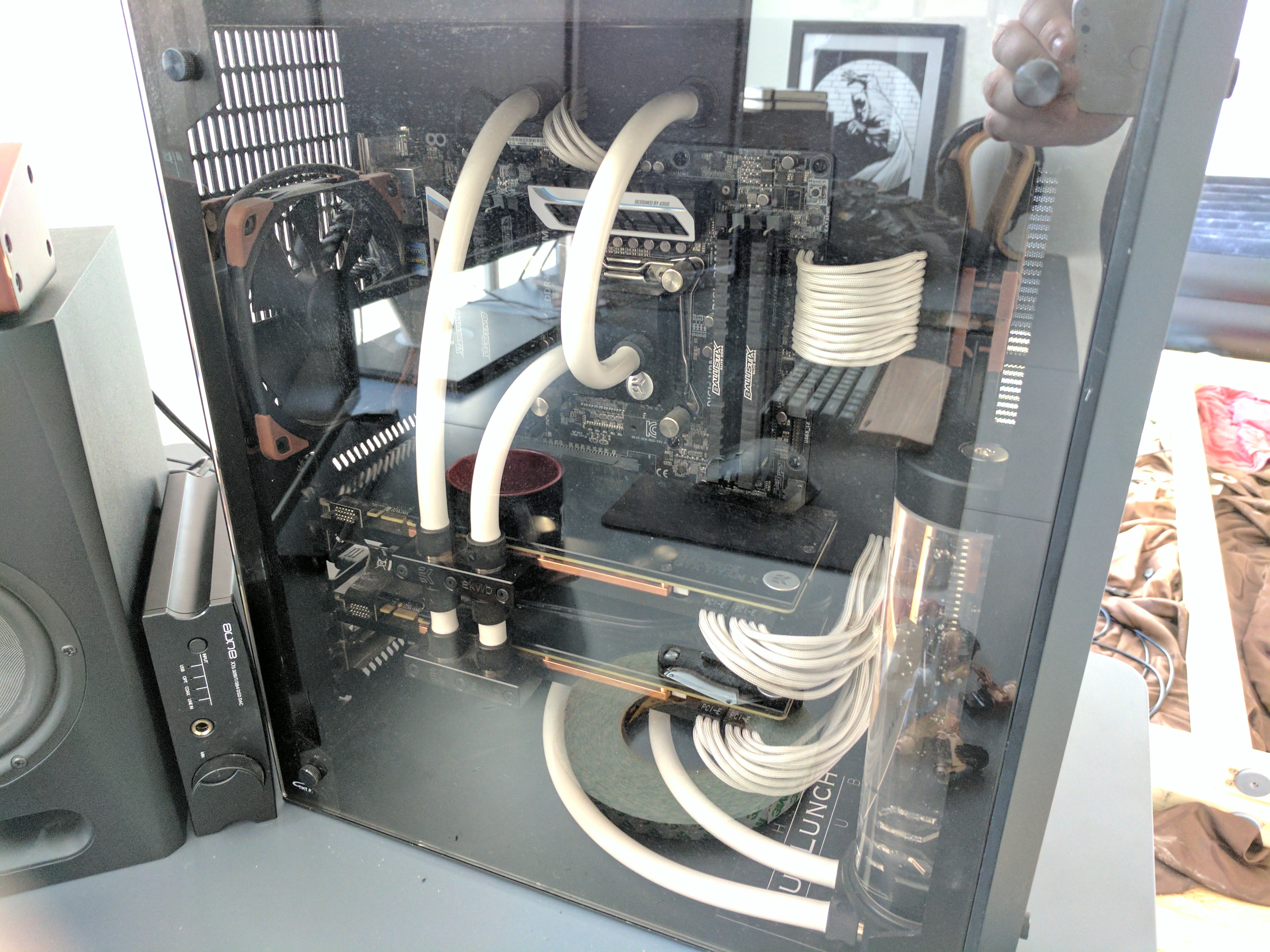
For my first custom PC build this ended up being very successful, even if it has taken me 8 years to actually document it. I believe I met my goals set out in the start of creating a high quality PC with a clean look that wouldn’t quickly go out of date. Below is an image that was taken a couple of years after the initial build when the PC was still my main desktop PC.
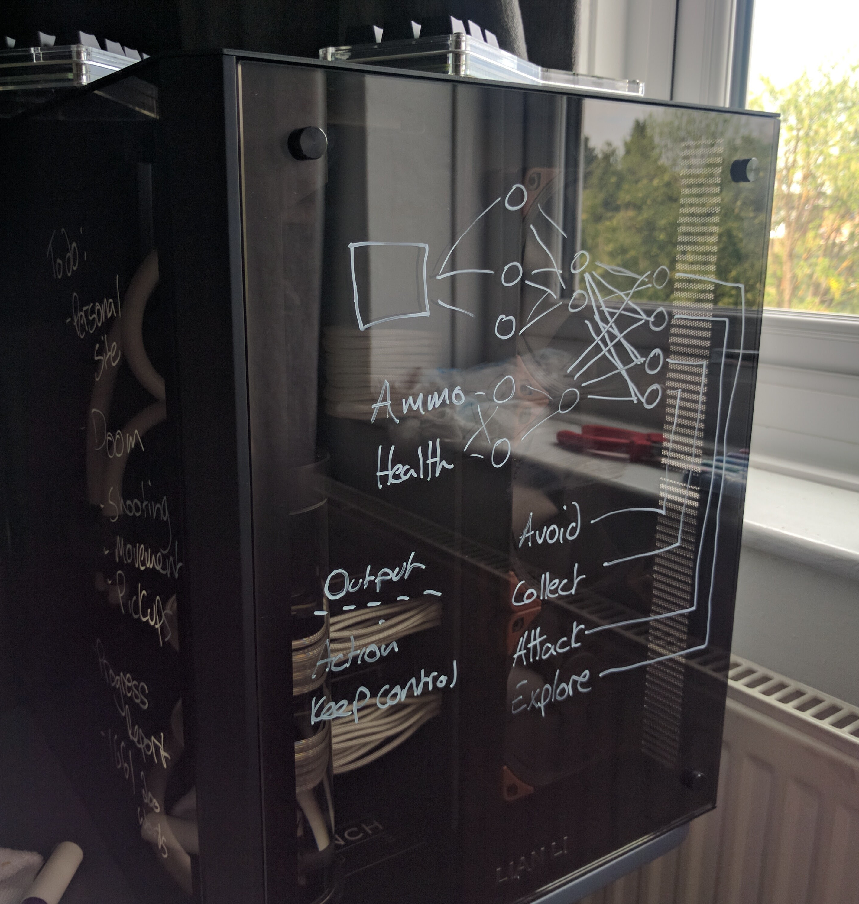
There where some other benefits I found to using the case that I hadn’t considered when building it. I discovered that I could you a special type of pen and use the large glass surface as a whiteboard.
This machine is still used as a compute node within my home Kubernetes cluster, it is now no longer the most powerful machine as I begun to integrate 3090s for the added VRAM. The observant will realise that a custom PC built this way does tend to mitigate the advantages of up gradability as many of the parts are custom built around the components. This meant that instead of simply upgrading the GPUs in this machine I ended up creating a new machine with air cooling when moving to more powerful GPUs. However I will be keeping this computer intact as a time capsule into this project and it’s still pretty nice to look at.