IBM Mouse Retrofit
Introduction
For a while now I have been wanting to use a more appropriate mouse with the other hardware I use in my main computer setup. This mainly consists of a FSSK keyboard that is a modern product that uses IBM model f buckling spring keys in a Model M style housing. I also use a DELL P1110 as my main monitor. I have a plan to use a IBM PC 5150 as a USB-C docking station as well so my setup doesn’t really suit modern gaming or productivity mice from companies such as Razer and Logitech. The closest I have been able to find and was using is the 8bitdo mouse coloured to look match their other NES accessories. However as shown it is not a perfect match and the red buttons don’t really fit, instead of waiting and hoping that they release a IBM Model M colourway like they have with their mechanical keyboards I decided to get an older mouse that matches the keyboard.
IBM Mouse
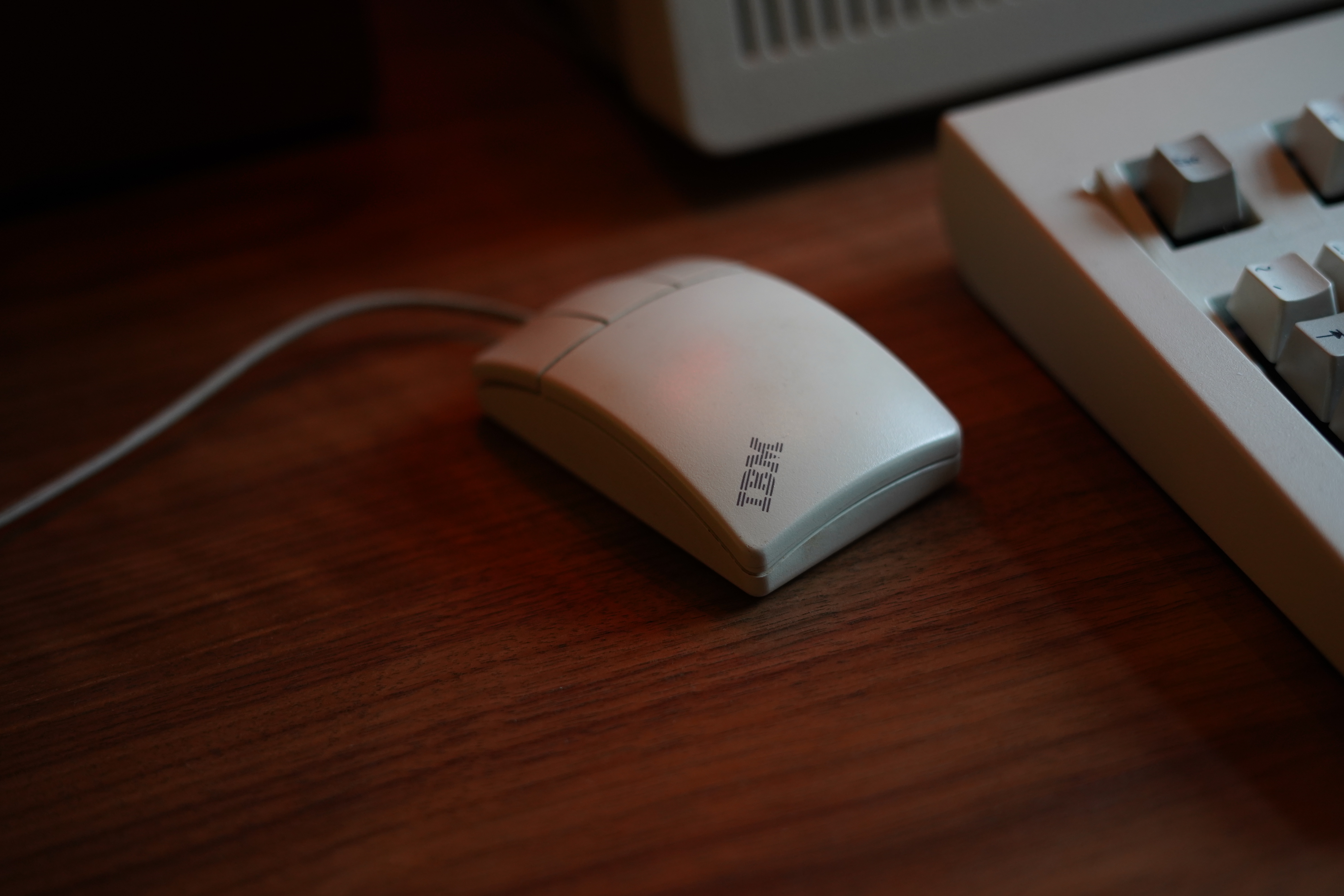
I managed to find this mouse on eBay that I think would match my setup well. There seem to be many Logitech branded mice that are identical so I’m guessing these are rebranded Logitech mice that IBM shipped with some of their machines.
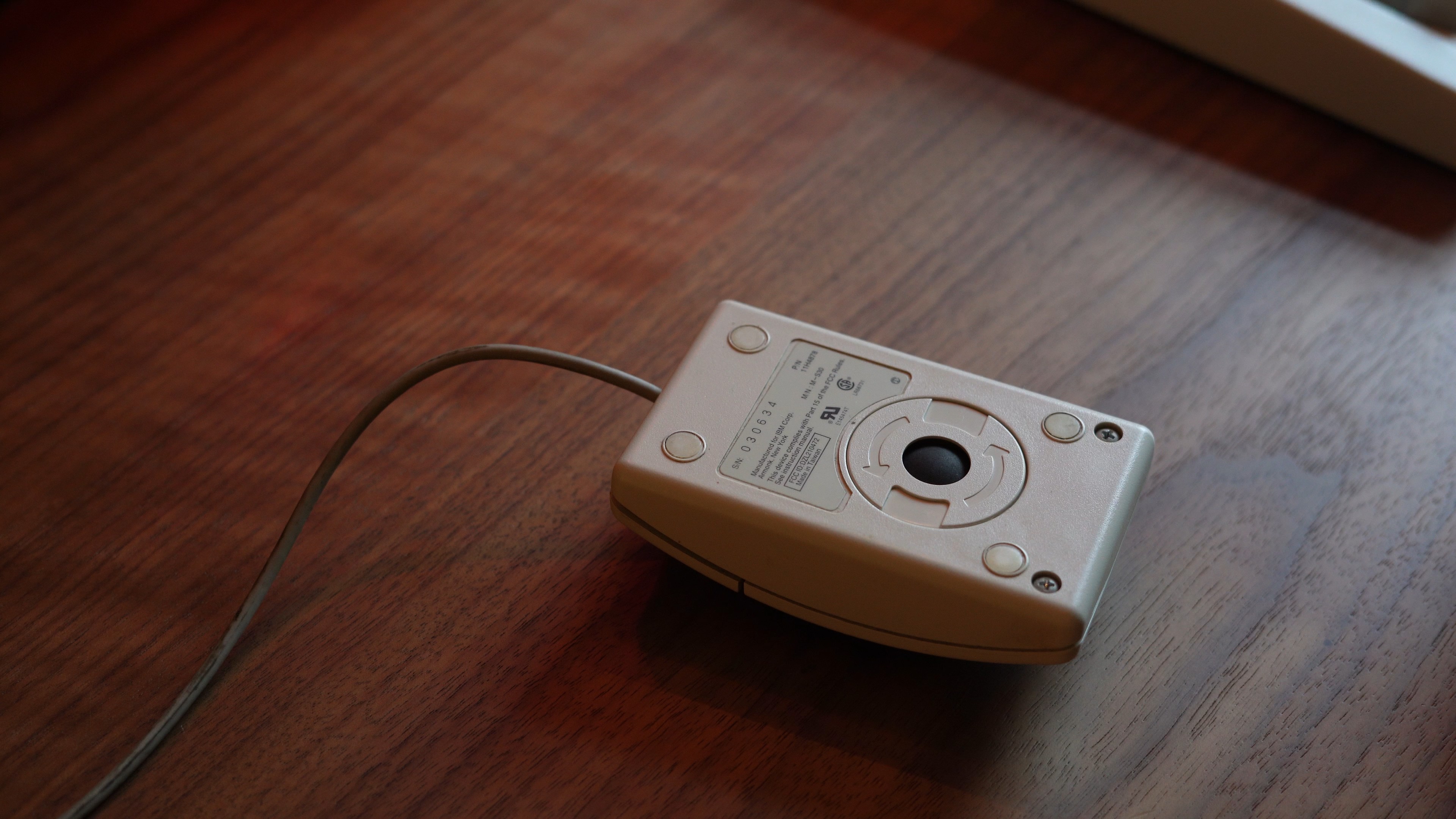
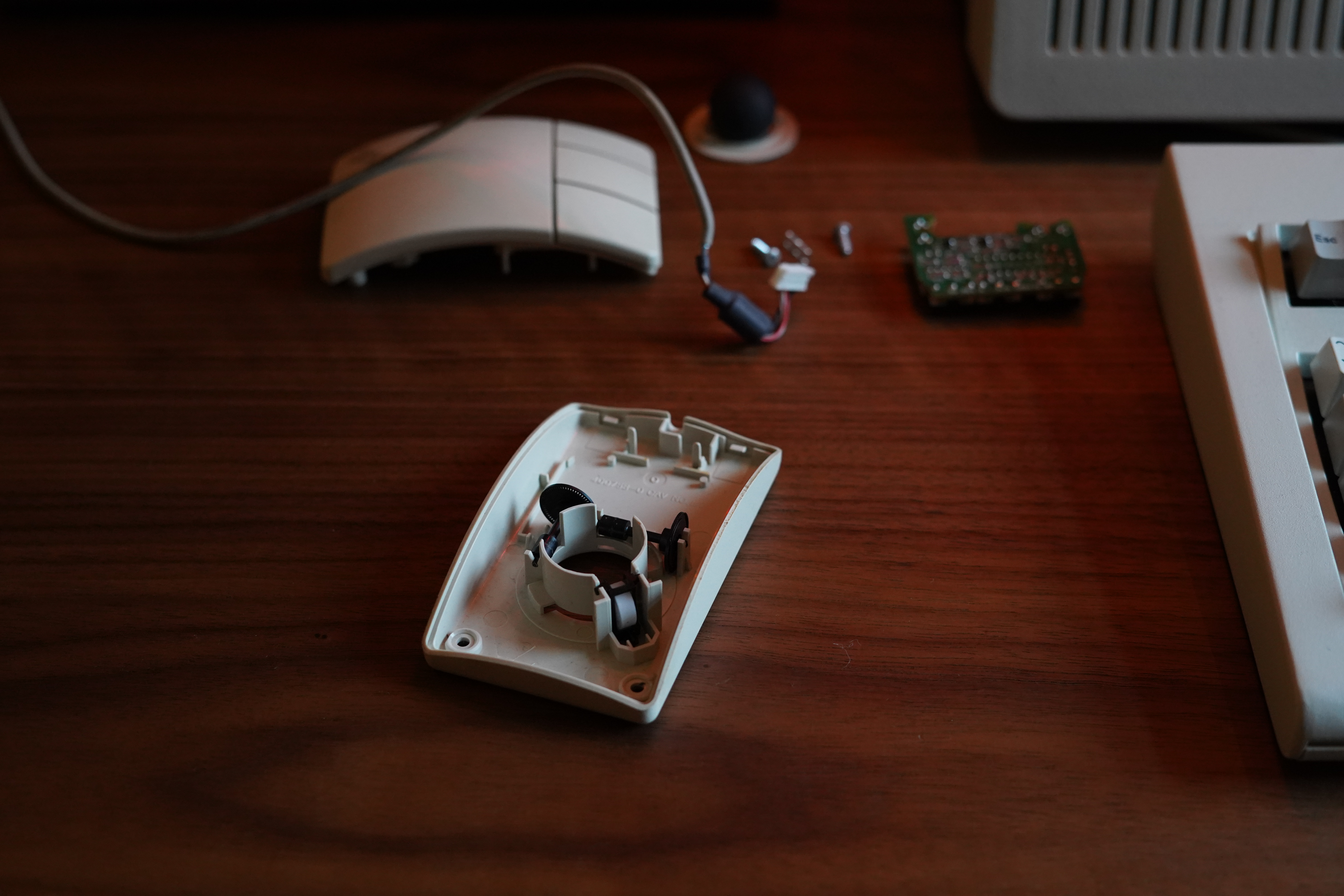
The main issue with this mouse as shown in Figure 2 is that it is a ball tracking style mouse. This means that there is a small ball that rolls across the tracking surface. These mice tend to have low tracking resolution (at least this one does) and can be unreliable on certain surfaces or when the ball becomes dirty. I did hook this mouse up using a PS/2 to USB converter and was able to get it working with my main machine, however the performance was appealing meaning that I couldn’t stick with it. Unlike keyboards where you can get pretty old models still performing as well or sometimes better than modern counterparts this unfortunately is not the case with mouse technology.
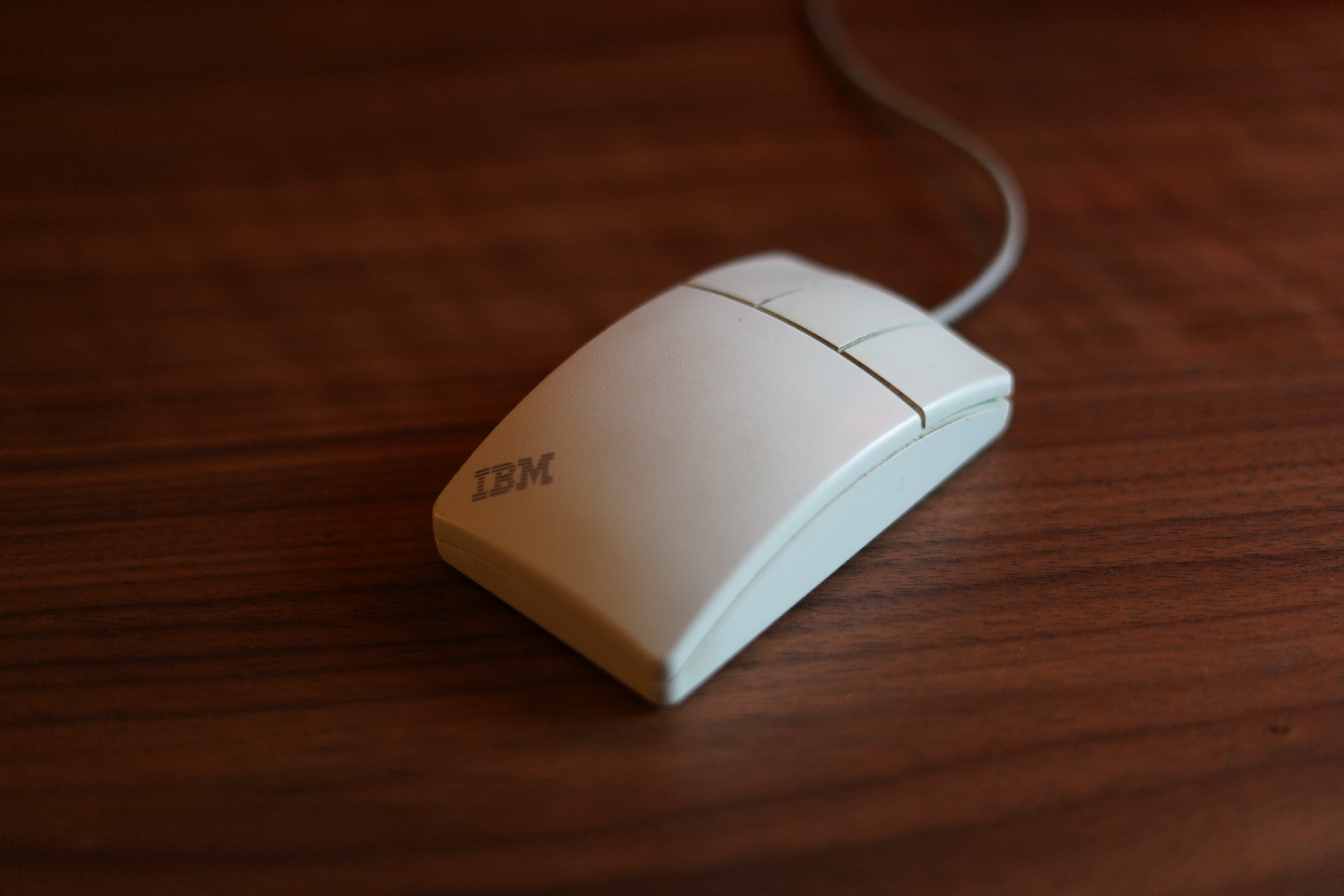
As shown in Figure 3 the mouse also only has three buttons and lacks a scroll wheel. This however is easily overcome in software as I will show later.
Razor Gaming Mouse
Given the poor performance of older PS/2 roller ball mice and only being able to get modern mice in styles that clash with the rest of my equipment I decided to retrofit newer mouse internals into the IBM mouse. In order to do this I needed to find a mouse where the sensor roughly lined up with the position of the ball mouse opening, as I didn’t want to make any external modifications to the IBM mouse. In order to do this I needed to be able to see the mice in person before buying, this limited my options for mouse brands as the only place I could think of that still exists to go and handle a large number of mice is the Razer store here in London.
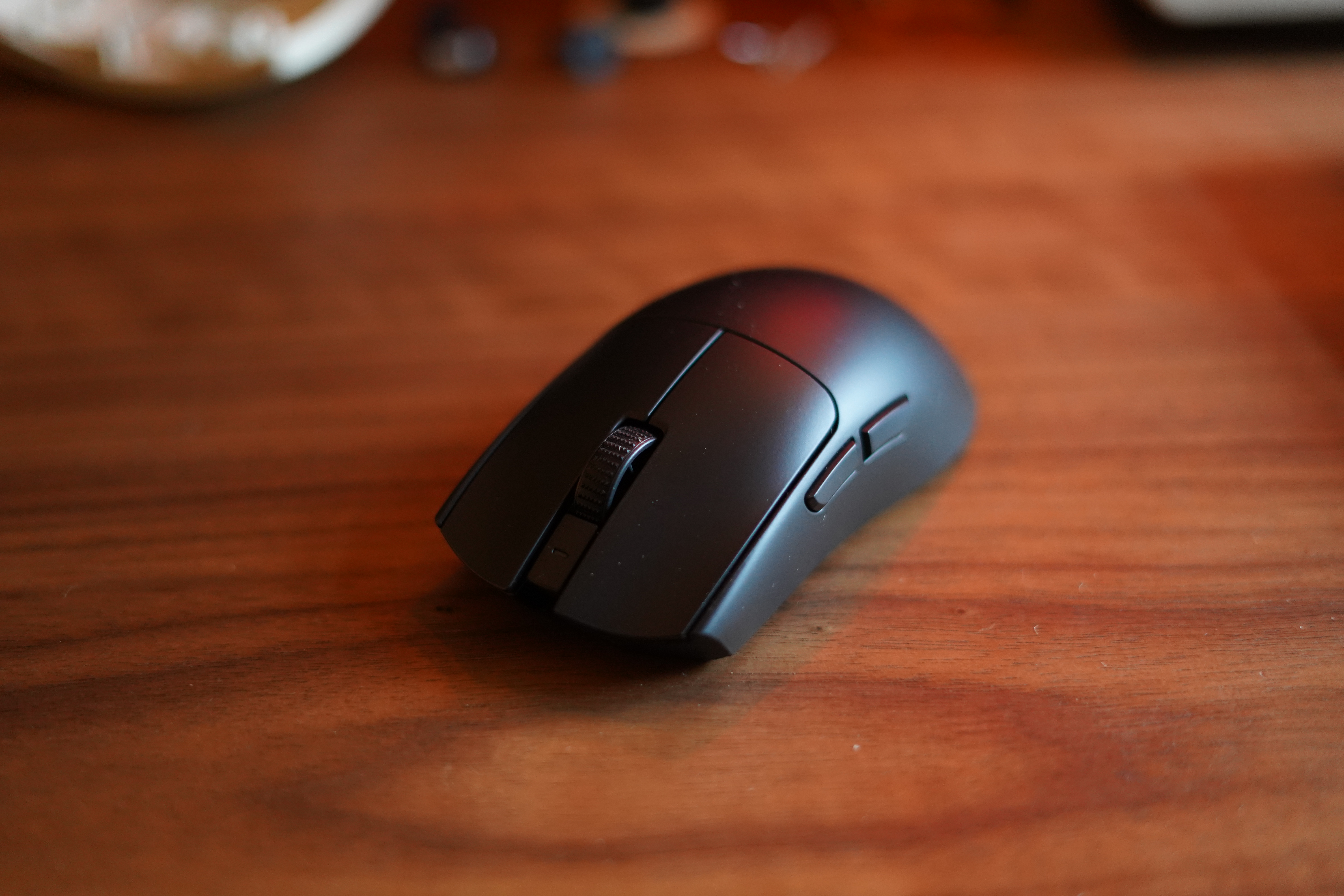
After taking the IBM mouse to the store and comparing the sensor positioning I decided to get the Razer Viper Pro 3, mainly because it had a high polling rate that worked wirelessly and wired, along with what looked to be good spacing between the buttons and tracking sensor.
Teardown
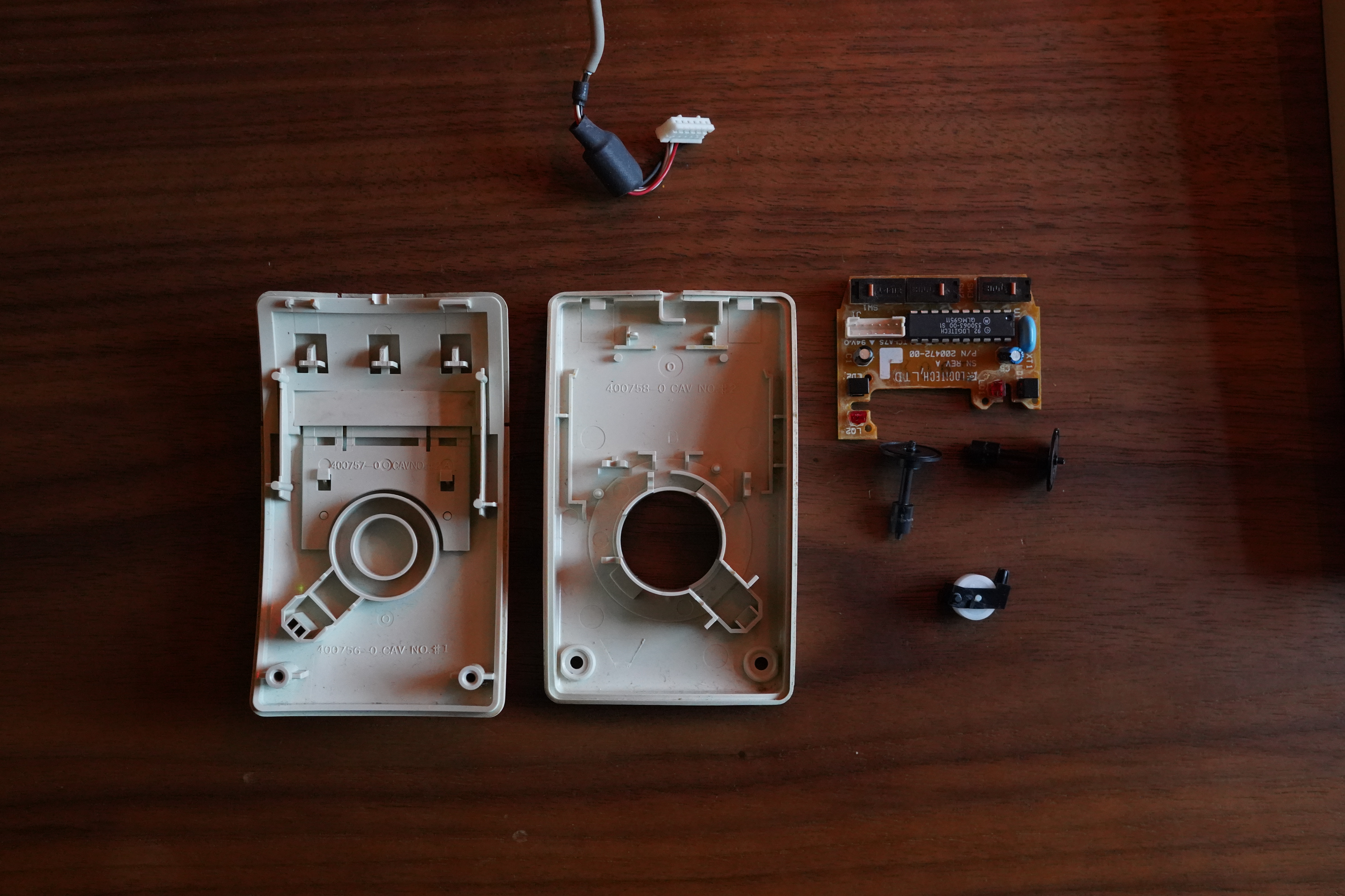
Firstly I disassembled the IBM mouse. In Figure 5 you can see the component parts of the mouse, this was interesting for me as I had never really taken apart a ball based mouse before, they were on their way out as I was growing up and so most of my experience is with optical mice. It was interesting to see that they used optical sensors that detect slits in a disc that spins as the ball rolls, these sensors are labled LO1/LD1 and LO2/LD2 one for each axis of rotation, I assume LO stands for light output and LD and light detector given their use. How these are arranged to detect movement can be seen in Figure 6.
This however did leave me with one question given that the enoder wheels didn’t seem to have any features that would allow the sensor to know in which direction it was rotating. However after a quick google I found this answer, basically there are two light detectors per sensor offset in the horizontal axis, meaning that you can detect the direction of rotation by which of the sensors detects light first.
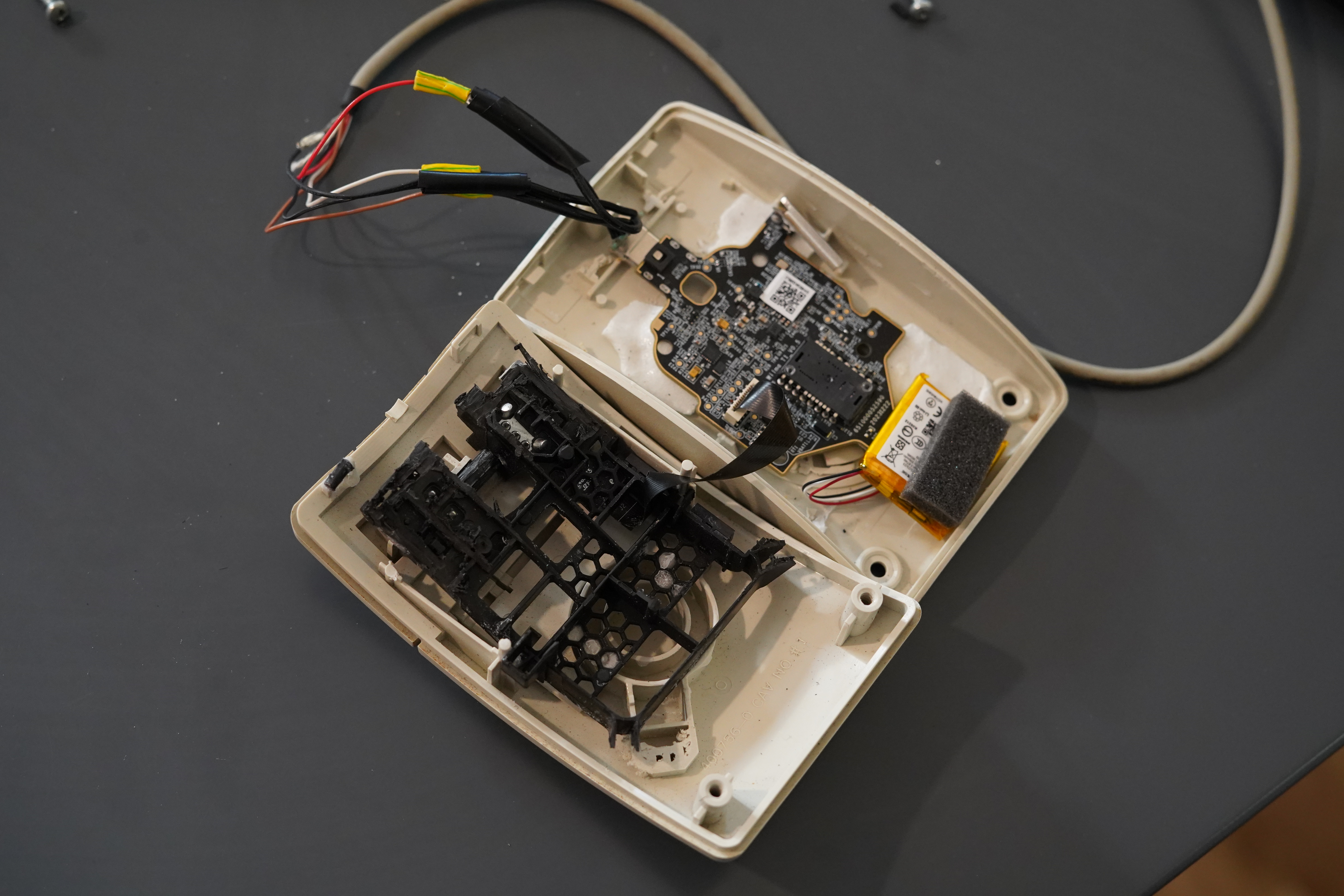
After tearing down the IBM mouse is was the turn of the Razor mouse to be disassembled. This was also pretty easy although care needed to be taken as the upper and lower portion of the mouse contain their own PCBs, connected by a ribbon cable. After disassembly I was able to extract the components needed for this project, shown in Figure 7.
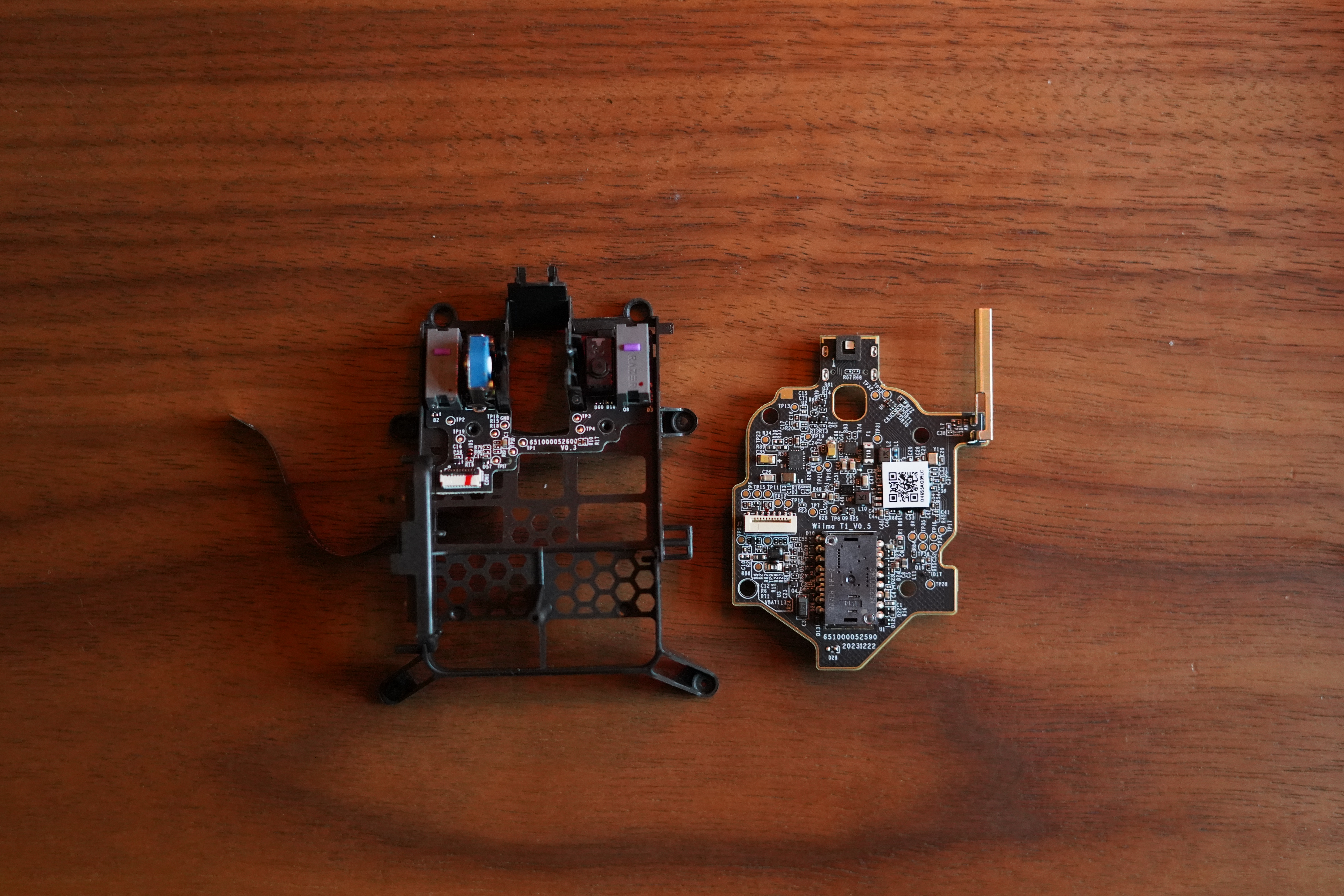
Here we just have a main board that contains the sensor, USB-C port and connector for a small lithium-ion battery and a daughter board that contains the left and right click switches the rotary encoder for the mouse wheel and another switch used for clicking down on the mouse wheel. The fact that the daughter board is mounted to a plastic frame is rather convenient as it allows me to modify it to fit the new mouse and brace itself against the bottom of the mouse.
Modification and mounting mouse buttons
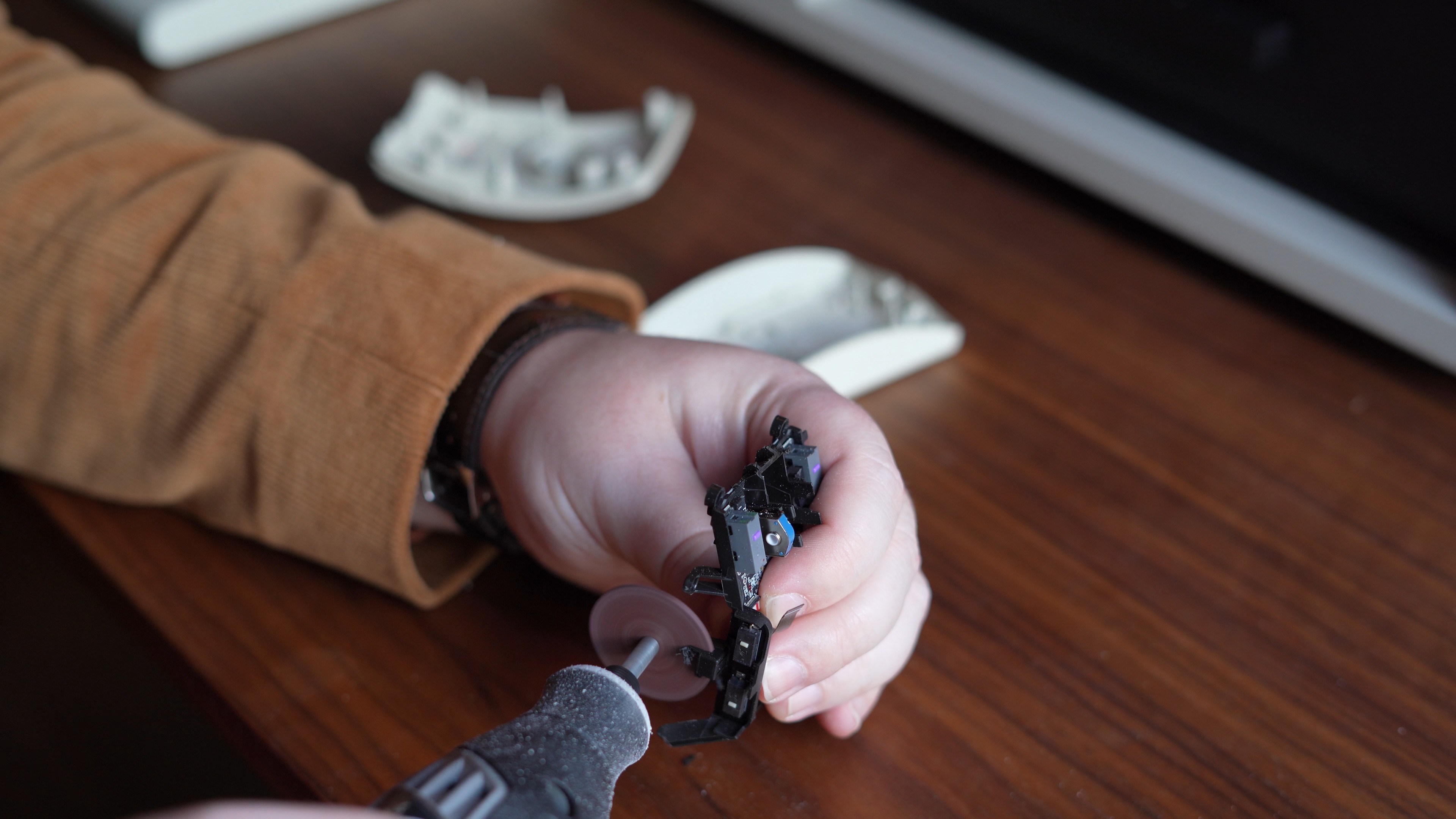
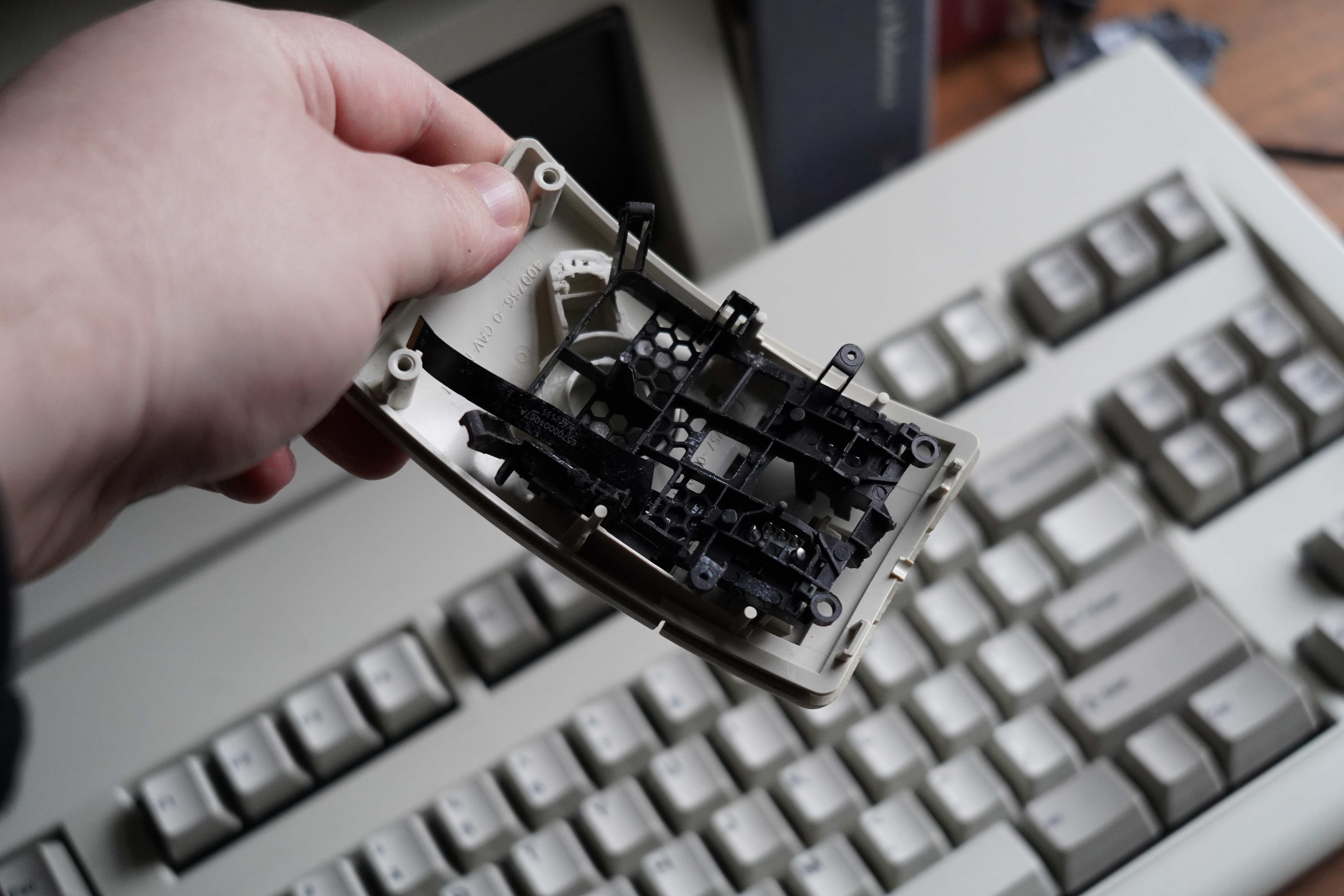
The first modification I made were to the plastic bracket holding the mouse buttons PCB this was done in order to be able to mount it to the top of the IBM mouse so that the buttons where in the right position. This was done by just gradually cutting away parts of the structure that were interfereing with the upper part of the IBM mouse. I also had to be careful when cutting some parts as the ribbon cable was connected to the side buttons that were permanently attached, I wouldn’t be using these buttons but if I damaged the ribbon cable then the mouse would no longer function.
It was also necessary to make some small modifications to the top of the IBM mouse in order to fit the shell and buttons but once this was done it was possible to position the buttons perfectly for the buttons to work.
In Figure 9 I’m showing the mouted upper PCB in the plastic mouting structure attached to the IBM mouse, this also allowed for adding a bar in the place of the scroll wheel, this ended up being in the perfect position for the middle mouse button to function correctly.
Mounting Sensor and PS/2 Cable
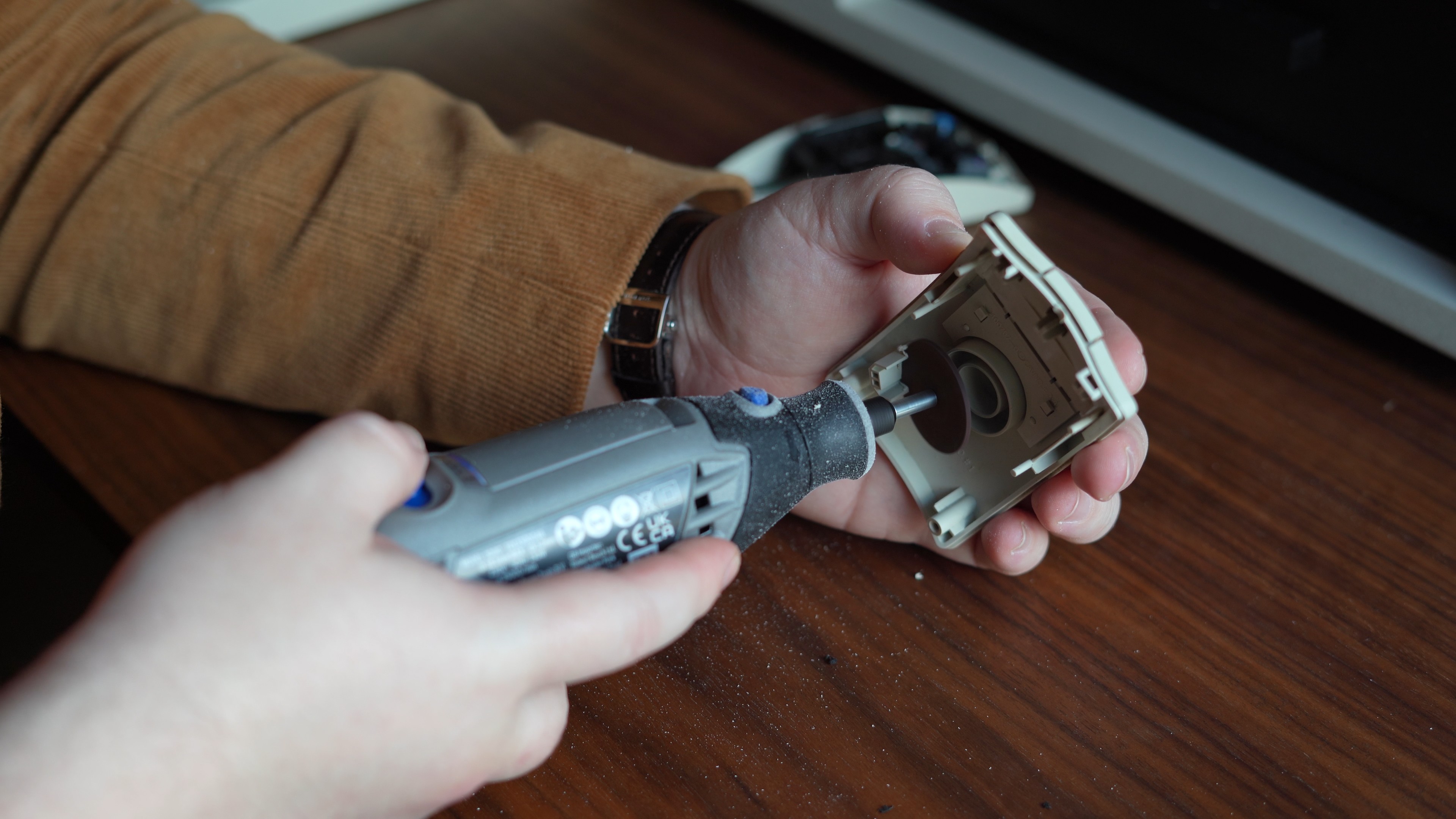
I now needed to mount the sensor in the bottom of the mouse. This was pretty simple compared to the buttons, all I needed to do was remove the plastic needed for the ball mouse and then mount the PCB in the right place that the sensor will line up with the hole left by the ball. The more complicated step of this process was to solder the PS/2 cable to the USB-C connector so that it could be used with the new mouse internals, leaving the external appearance of the mouse identical to before the retrofit.
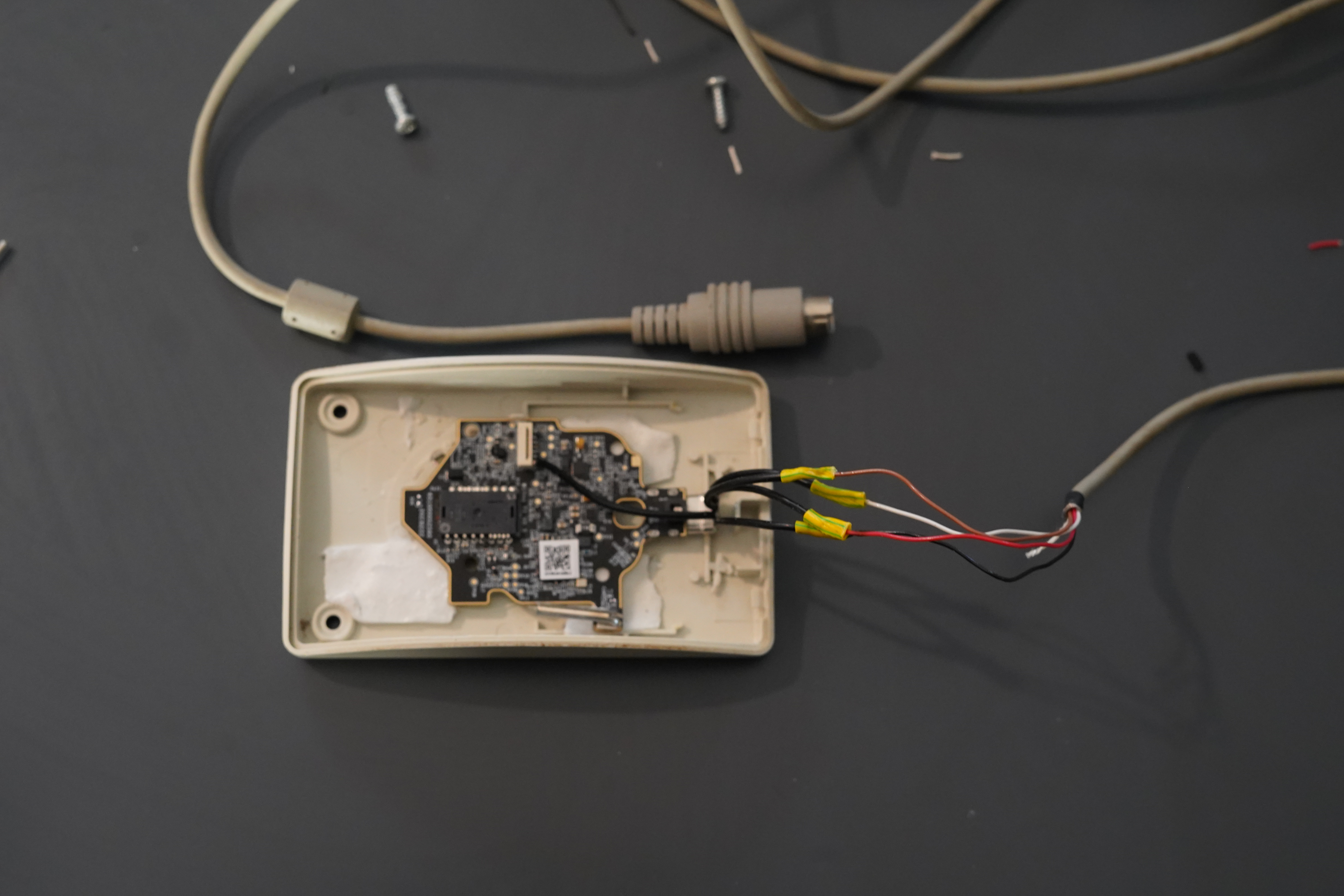
Luckily figuring out the pinout of a passive PS/2 to USB adapter was pretty easy and then soldering the right cable was just a case of matching the colours to the correct pins. Once the cable was soldered I could finally re-connect the battery (allowing the mouse to be used wirelessly, although removing the calbe involves splitting the mouse back apart.) and then connect the two halves with the ribbon cable.
This now effectively gives the final mouse that can be used with any passive PS/2 adapter or wirelessly using the razor receiver.
Conclusion
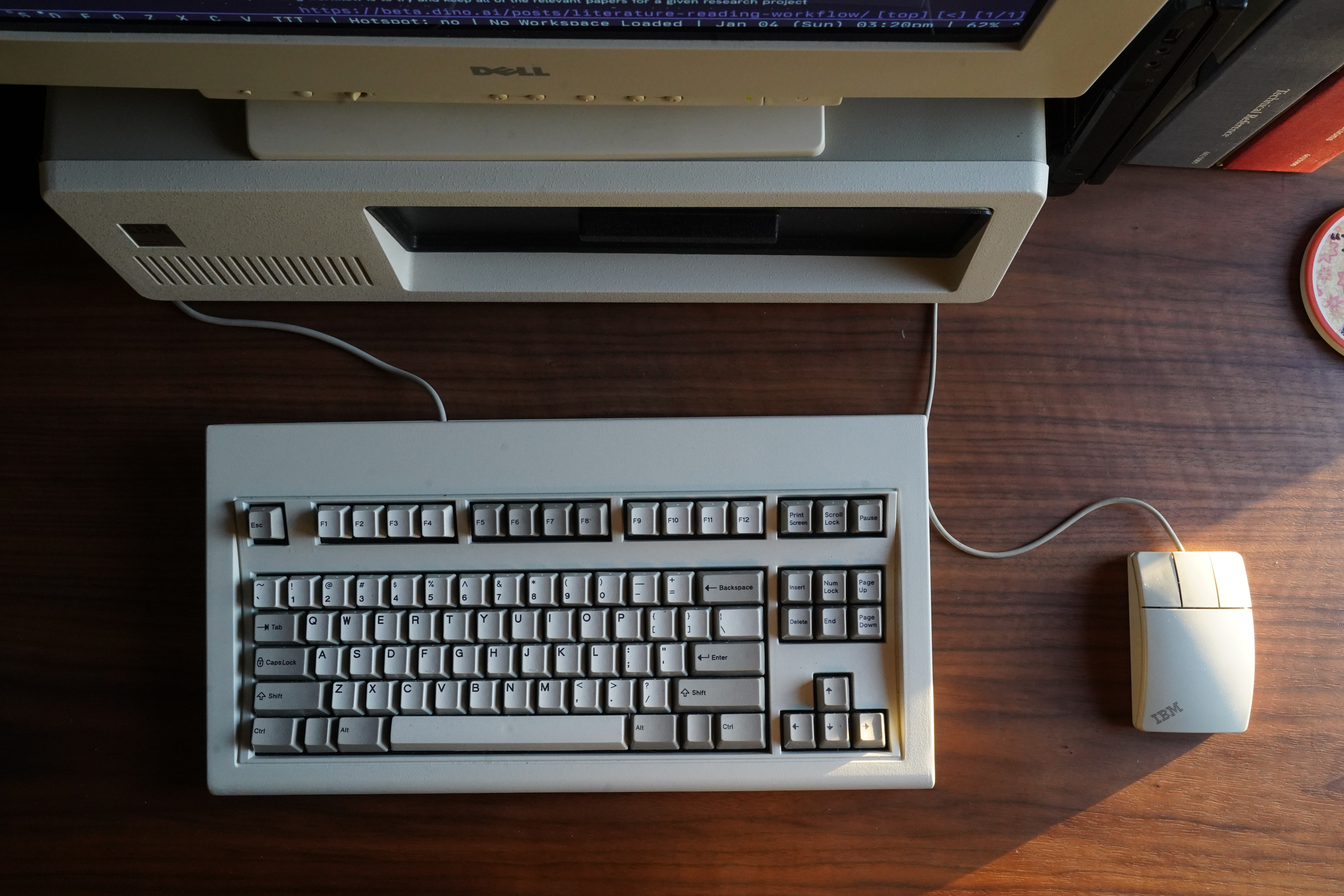
In the end it was rather a quick process in transplanting the new mouse internals with little effort being needed to get everything working. I think part of this was picking the donor mouse in person giving the best chance of most of the components lining up, as well as a bit of luck. It was a nice little project to complete during the Christmas break. Below I show the mouse in my main desk setup where I work and I think it fits in perfectly. I am working on turning the IBM pc into a full USB-C dock with working 5 1/4" floppy drives so will hopefully post about that soon once I’ve made some more progress.
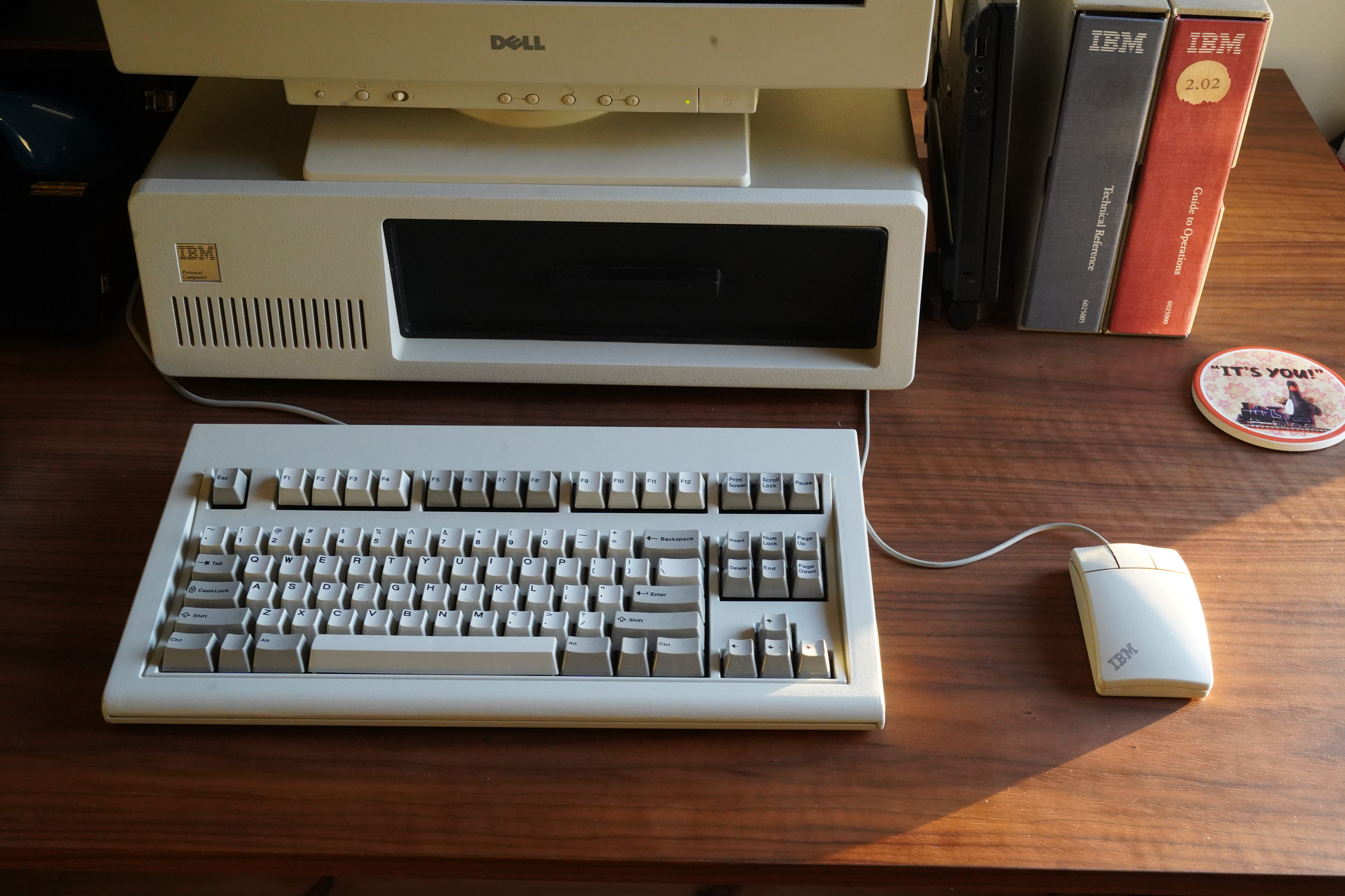
The mouse also fits with the Model FSSK keyboard perfectly, exactly what I was looking for at the start of this project.