Sony PVM-6041QM
Introduction
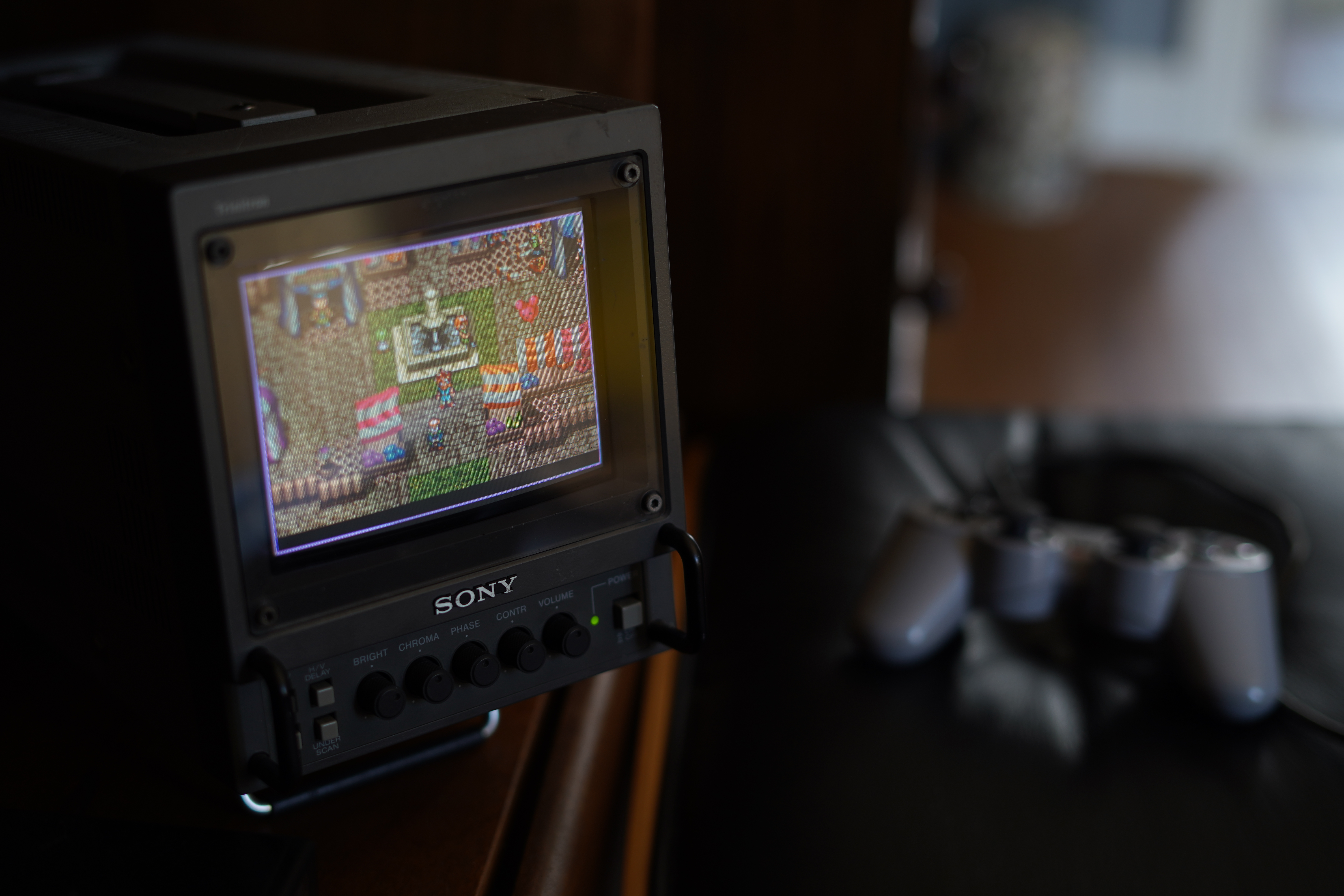
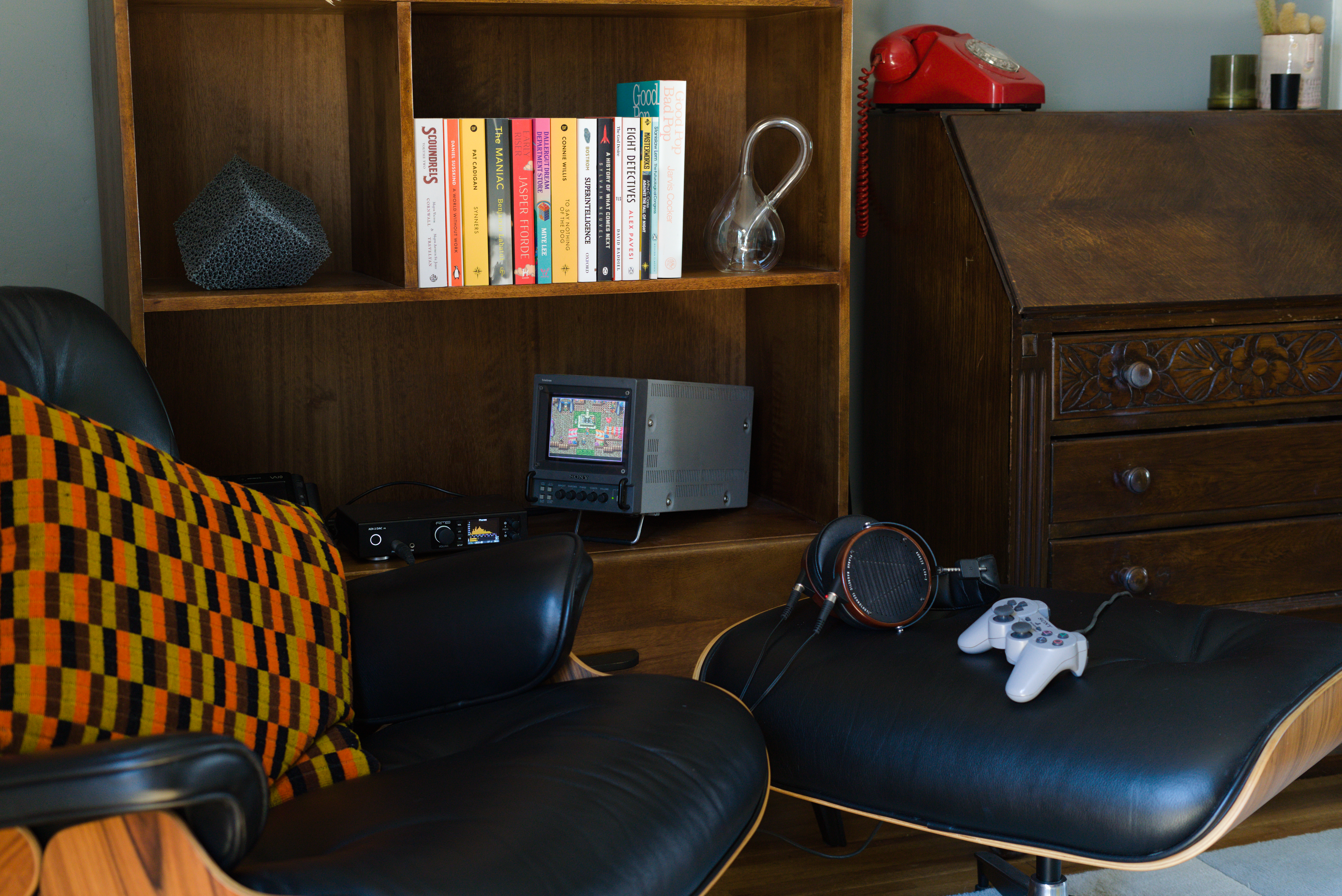
I recently acquired a Sony PVM-6041QM CRT. I thought it would make a nice screen for showing album art in my reading/listening area I created. It now has also doubled up as a screen to play retro games on, mainly 16bit systems.
Setup
Outputing an Image
Outputting an image to this model is pretty straightforward, it receives RGBS signals that can be easily converted with a VGA to Scart adapter and then using a SCART to RGBS cable to hook up the computer. In my case I was using a modified Sony Vaio VGN-UX1XN although the modification is just an upgraded CPU so has little bearing on getting this monitor to work.
Although the hardware setup is pretty simple getting Linux (with intel onboard graphics) to output a signal the monitor will sync to is slightly harder. I don’t know the details but as far as I can gather the intel onboard graphics are not able to run at a slow enough clock speed for a 15KHz CRT, thus you have to use a “super resolution”. This involves outputting a much wider resolution, the modeline used in my setup is below:
"1920x240_60.00" 36.00 1920 1968 2160 2400 240 243 253 259 -hsync +vsync
This outputs a much wider image and appears squashed on the CRT when displaying. However it is possible to fix this scaling issue when outputting through X11. Here is my xrandr command for outputting to the CRT.
xrandr --output VGA1 --primary --mode 1280x240_60 --scale 0.25x1
This resulted in displaying an image with the correct scaling, however the position and geometry of the image was not great. In the next section I show how I adjusted the geometry to improve the image.
Adjusting the image
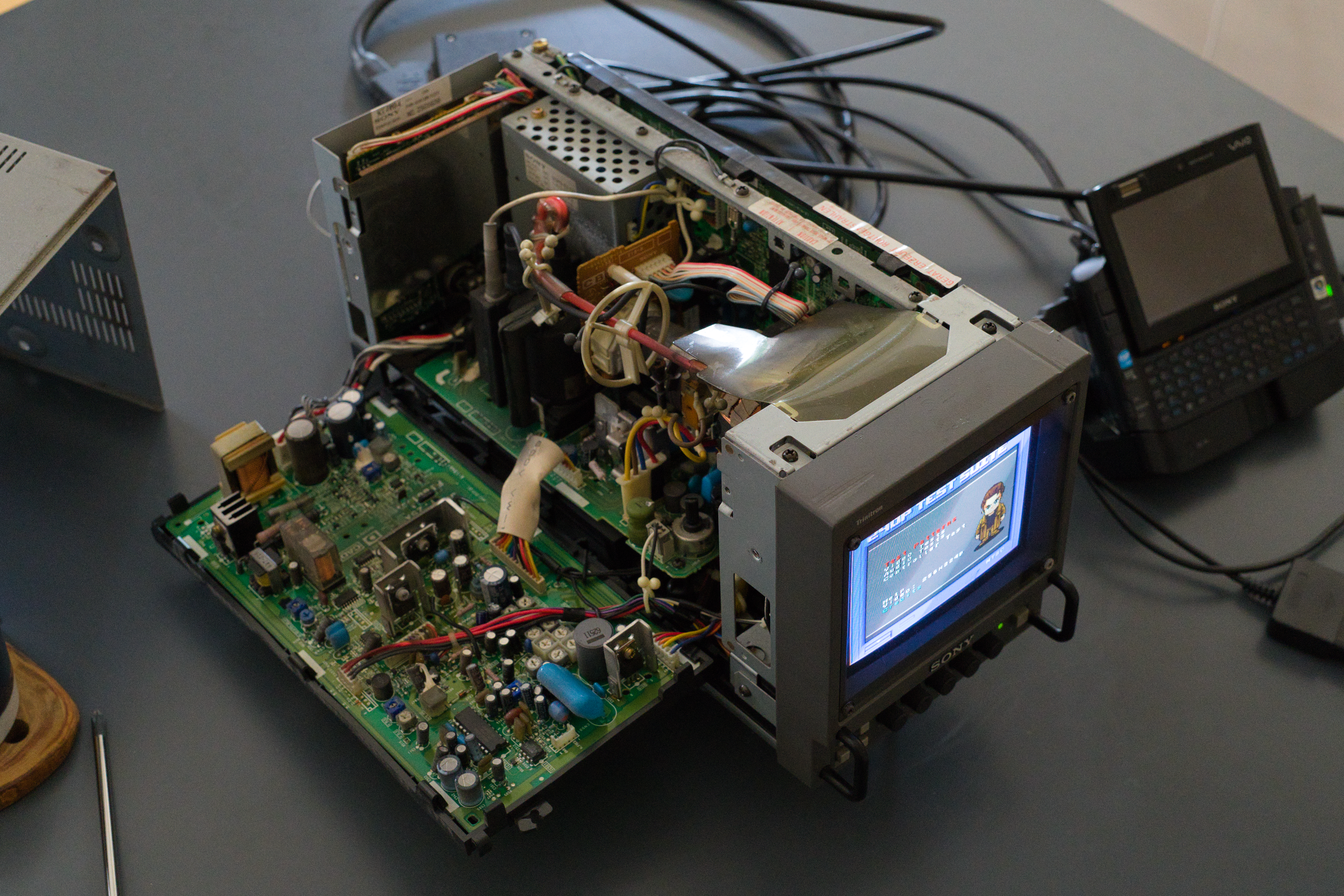
The internals of the PVM-6041QM are packed very tightly and CRTs can store large amounts of energy making then particularly hazardous to work on. I wouldn’t recommend adjusting yourself unless you are experienced. Fortunately the service manual is freely available online, I have also uploaded it here to make sure the links on this doc don’t die.
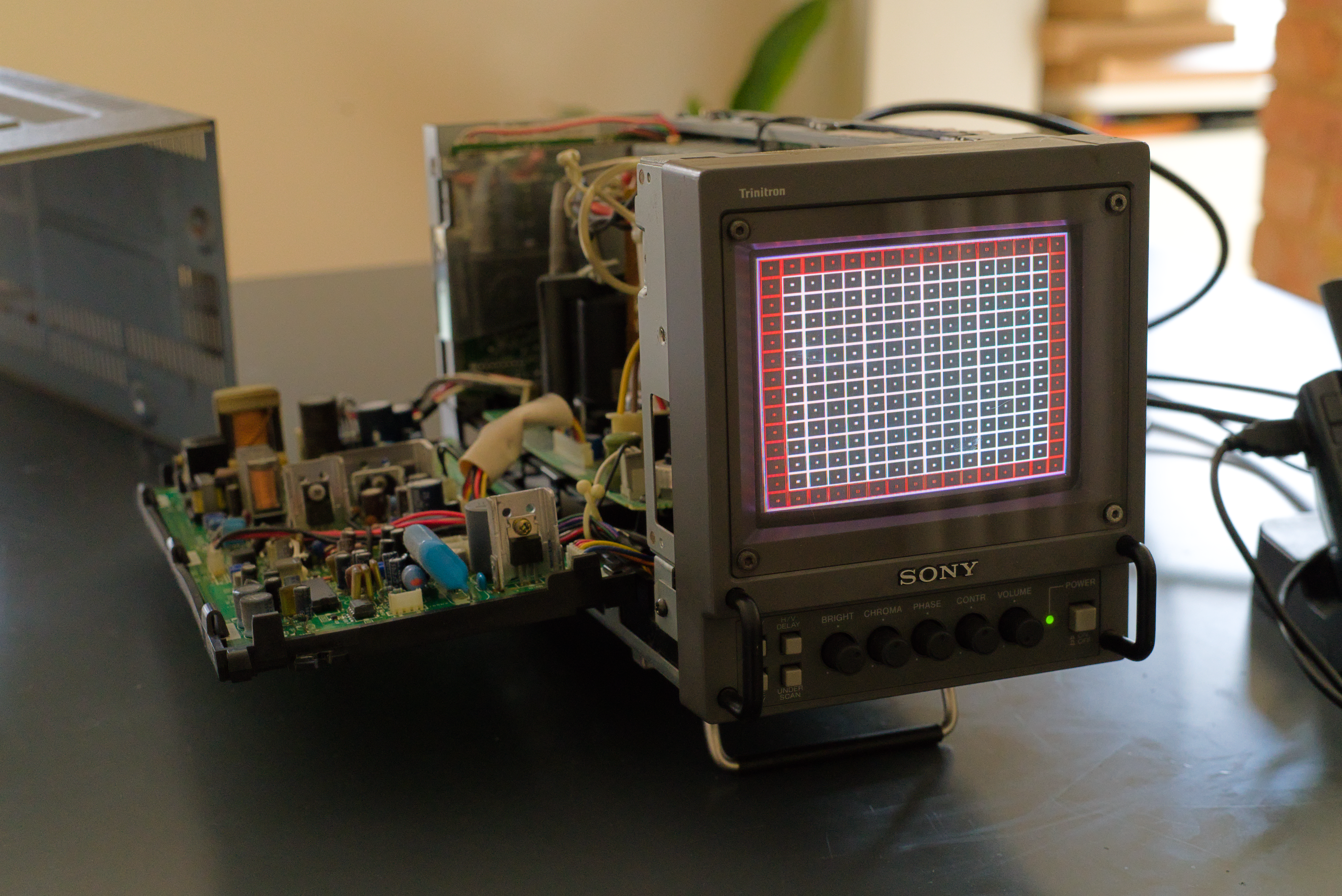
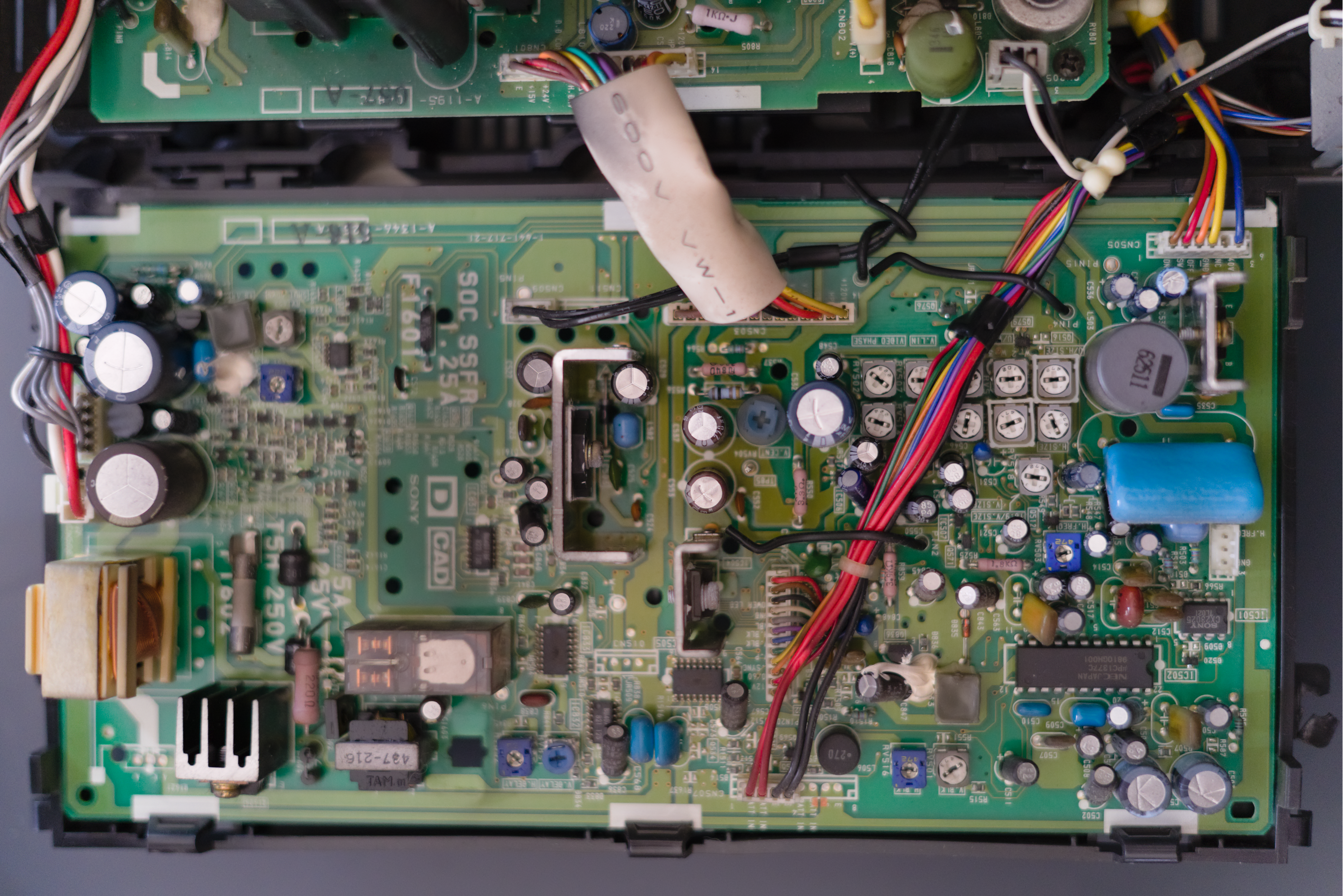
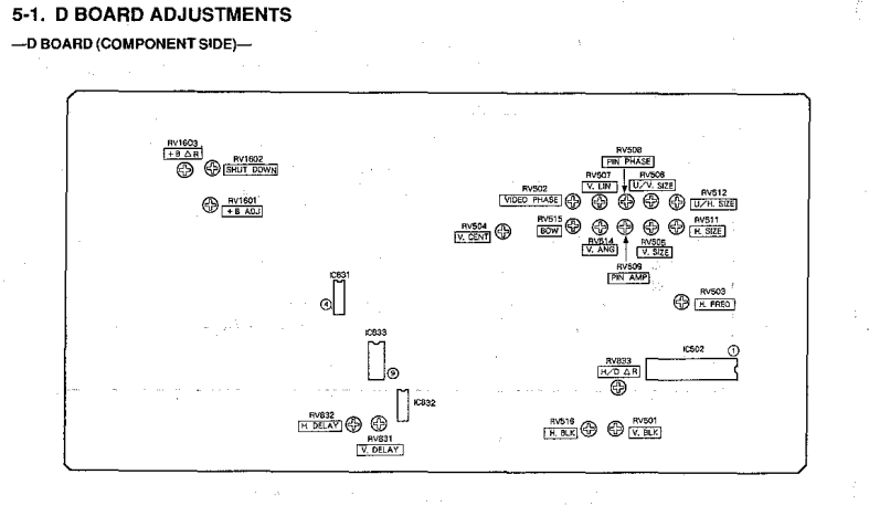
Once removing the case the D-Board can be unscrewed and hinged downwards as shown in Figure 2 above. This gives access to the pots for changing various geometry settings for the screen. As you can see in Figure 2 the bottom of the image is slightly bowed. In the figures below I show the D-Board (Figure 3) along with the diagram in the operators manual (Figure 4) for the various pots.
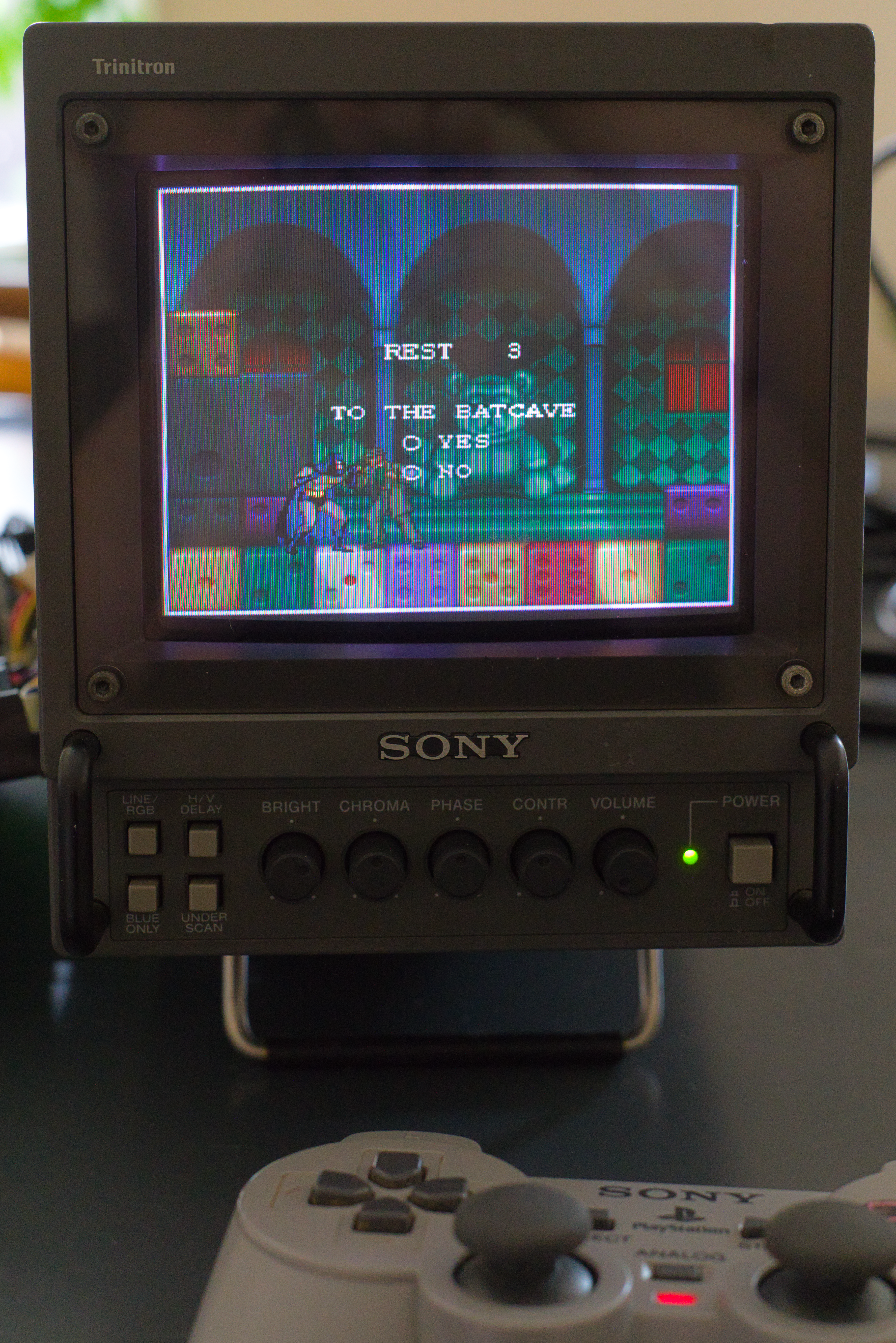
For adjusting the image I used the 240p Test Suite specifically the SNES rom. This isn’t the best rom for adjusting colours but the colours looked fine to my eye and I was only interested in adjusting the geometry anyway. I was running this rom through emulation from the computer (Sony Vaio) that would primarily be providing the signal to the CRT when in it’s final location.
Finally I was able to get the image to look somewhat correct, as shown in Figure 6. The geomerty isn’t perfect but it is plenty good enough for a first attempt and I’ll probably have another go at improving it once the remaining issues get on my nerves.
Finished
All that remained was putting it back into it’s home in my reading corner along with my music listening setup. For now I will enjoy mainly retro gaming on the monitor and using it to display the currently playing album artwork.
In the future I aim to create my own TUI (Terminal User Interface) that can be controlled using the connect PS1 controller to allow for a variety of use cases. This will probably be similarly built to my leader based workflow outlined in this post, just more tailored to a controller based input method.